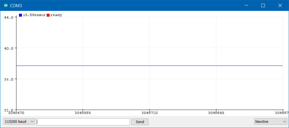
The stabilized value is difficult to get, it needs precise tuning of the angle. But each time you miss the required precise angle, the value is offsetted by about PI rad (hence the above screenshot, at 38 rad, after a few trials).
If you continue turning the motor, between “point left” and “point top left”, there are several of those “stabilized” angles. Each time you cross them, the value is offsetted by about PI rad.
If you continue turning after “point top left”, you come back to the original behavior, but with the accumulated offset:
I did some more tests and discovered that the issue only occurs when going through my SimpleFOCShield! If I remove the shield and plug the sensor directly on the Nucleo-L476RG, it works like a charm. I’m a bit puzzled. How can the shield interfere?
I have no idea how would shield interfere
It might somehow introduce some ground plane noise or something like that, but I have never had any such issues sofar.
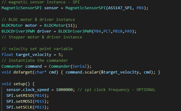
However, what might be an issue is the pinout you have chosen for your shield. Make sure that you do not use and of the SPI pins for the PWM.
So avoid using pins 13 and 11. And maybe dont use the chip select pin at pin 10, but if you can put it somewhere esle so you can use pin 10 with your shield for pwm.
Now I have not really understood your problem with the sensor, were you able to have any values out of it or just the noise?
I’m happy that you’ve found a solution that works for you, but the library should be able to work without any problems with the AS5048A. It was one of the first sensors that has been supported by the simplefoc library. So and as far as I know, many people has used it with the library out of the box. But every mcu is a bit different and every sensor as well, so if there is one thing we have learned with simplefoc is that you never know with hardware
That’s very interesting. I have no idea what that could be, but I’d be really interested to get to the bottom of this.
We did have some issues with clock signals of the spi for the stm32, this should be resolved in the dev branch. @runger has rewritten the spi sensor implementation.
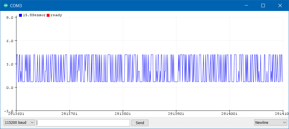
In your photos from before, you say that you move the motor 90 degrees but you always have the agle of 3 rad, just more or less noise?
Is this the behavior you’ve got?
Or your angle is read well, just you have a lot of noise and that is the issue?
From 0 to PI/2, no change in signal (“short” noise). From PI/2 to 3PI/2, the angle doesn’t seem to change but the noise gets taller. From 3PI/2 to 2PI, very strange behavior with stabilization at specific angles (with no noise) and sudden and permanent offset of PI rad.
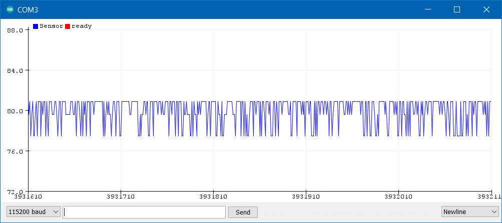
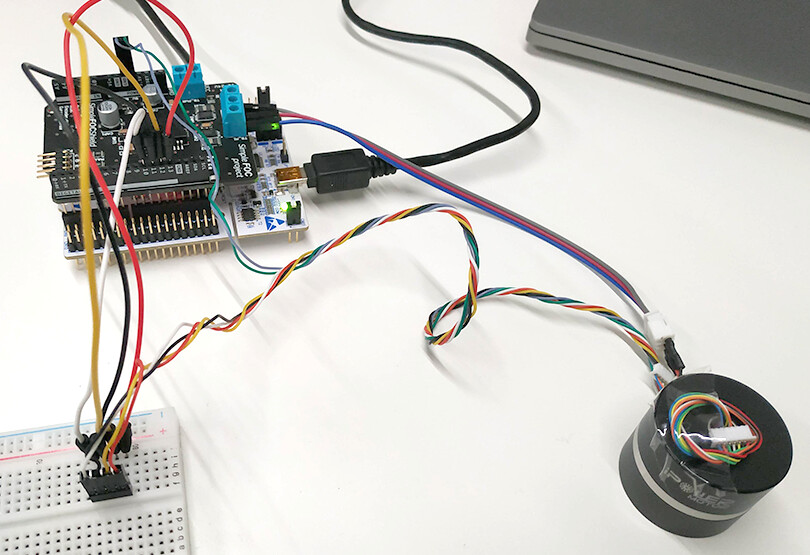
Now for the strangest part. If using a breadboard instead of directly plugin the connector to the shield, it works with both MagneticSensorAS5048A and MagneticSensorSPI:
Hi, just like to join the club with this issue. I’ve tried a lot of different things. With/without logic level shifter / with SPI1/SPI2/SPI3 and still getting issues. I will give the above flavors a go, it seems to be totally random though
If I hook it up to my arduino it seems to work flawlessly. Strange thing is, I’ve had this sensor working before without issue.
That works, my own script too. But once I start using it in combination with Loopfoc/move commands, I start getting spikes in my sensor reading.
Edit: initially I had almost exactly the same output as yours, but that was with a logic level shifter in between, corrupting the spi signal. Now I’m attempting a direct connection to 5V tolerant pins.
I was not able to get good readings with my AS5047 spi sensor using the 5v logic with the stm32 boards. I had to use 3.3V logic.
The breakout that I have has a small soldering connection to switch in between logic levels, you don’t have one?
I am not sure what is the best way to solve this issue except for using the same logic level as the board.
I have the AS5048A btw; I see the type is ‘wrong’ in my screenshot.
I’m not sure what breakout you mean? I did use two variants of logic level shifters that were not OK in terms of speed. I’m picking up two different types tomorrow (I hope they work).
I’ll update this post if I found a solution.
The thing that I cannot comprehend is that I only seem to get it if my motor is actually moving. If I move the encoder by hand and read the sensor I never see a spike.
Edit: reading another post about this issue you refer to the breakout of the sensor. Unfortunately the one I have does not have an easy accessible soldering bridge.
I have been experiencing exactly the same issue with my SimpleFOC shield V2.0.4. Wondering if there is an update or solution to it already?
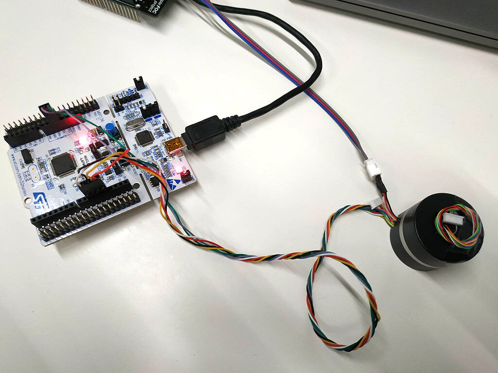
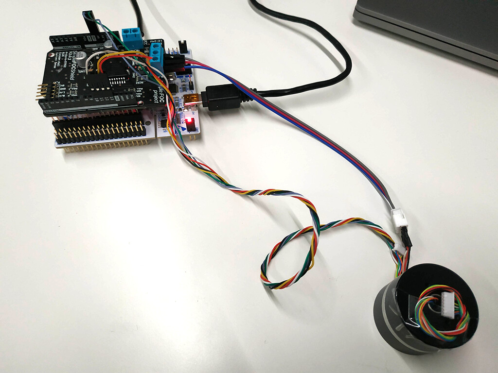
About my setup:
I am using the shield with my stm32 board to control the gimbal motor with an integrated sensor AS5048A. The reading is perfectly OK when the motor is not powered, but gave spikes when the motor is powered, as described in the previous posts.
I then tested another setup: I replaced the shield with a DRV8302 board. Problem solved.
Maybe it could be related to some grounding issue on the shield?
I think the only way to clarify this is to poke around with an oscope and logic analyzer, compare schematics, form a theory and test it, repeat. It takes time and skill. This is exactly the sort of thing that makes me a fan of picking one flagship board, not a shield but a whole board with MCU and all, and getting everything working. Just look at the sheer number of components on these boards. Nothing about this is simple or plug and play. It’s amazing that some people are able to cook up systems that work as easily as they do.