Hi together,
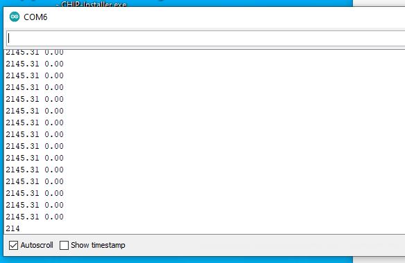
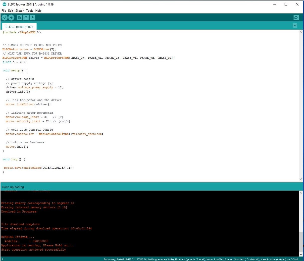
I have good news. Last thursday I soldered a 5V step up to 12V module between my powerbank and the control board and it works. At the beginning the control with the onboard potentiometer was very rough and I integrated a parameter “i” in the code at the weekend and set it first to 100 and then to 200. In the last command, the range of the onboard potentiometer is then greatly reduced, more or less calculated by this 200. I can now use the potentiometer much better to control the speed and feel that I am using the entire rotation of the potentiometer to set between 0 and 100rmp (I didnt count the rpms).
Here is the code for this:
so far so good, I still have 3 questions:
-1- The motor and the control card get very warm, around 50-60 °C I guess, and this causes a lot of power to be lost from the battery. Is it possible to reduce the power of the motor or is there another way of preventing heat build-up? I was thinking of changing the PID values, but I don’t know if this works with this board/combination:
// Set the PID values for the controll loop
motor.PID_velocity.P = 1.0;
motor.PID_velocity.I = 10;
motor.PID_velocity.D = 0.0001;
motor.LPF_velocity.Tf = 0.05;
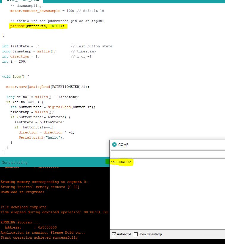
-2- I would like to use a separate poti with an integrated switch for the board. Is it possible to solder an additional poti to the existing onboard poti, i.e. to connect it in parallel, so that the speed can be controlled? I didn’t want to unsolder the existing 10kohm poti first.
-3- What does the command “motor.voltage_limit” do? At 4V the motor starts to make noise