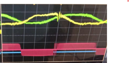
I am finding invalid switching during the transition. Please guide me which parameters i have to look for to resolve this issue. The top waveform are the 2 phase currents, the pink one is the differential voltage between two phases. The blue line can be neglected. The same issue keeps repeating during the entire motor running.
Sorry for late reply i am trying everything to solve the issue and found this paticular behavior. I have written the debug code to output the pwm duty cycles A,B,C using DAC and compare with the phase currents, i plotted the PWM DAC output and the phase currents
→ PWM A and Phase A current
Similar image for PWMB and Phase B current
But for the Phase C current is little different the PWMC is same but the current waveform is different as shown
→ PWM C and phase C current.
I tried changing every thing from MOSFET driver to Mosfet but the same result. Please suggest what else i can do to resolve this issue? First is it an issue or not an issue?
Is this with a motor attached? Transients like this will be filtered at the motor if one is attached.
Does your mosfet have any gate resistors? This would limit the slew rate if that’s what’s causing ringing, you could experiment with some different values.
If you change the driver pin ordering (e.g. change U and V phase pin definitions in firmware) does the artifact follow a pin or does it remain on the same physical phase?
Are you using custom hardware? Can you show a schematic?
Thank you for help one solution i found is, if i place a capacitor in the current sensing circuit the behavior of phase C getting distorted is observed as per the previous post. I removed the capacitors in the phase current sensing then 3 phases are coming similar but with distortion.