We are currently working with the GM-110-8 motor (https://shop.iflight.com/ipower-motor-gm110-8-brushless-gimbal-motor-pro197), and are able to get it working well in open loop position and velocity modes. We did some tests with the torque mode (FOC current) and need some help in interpreting the results.
Test setup :
No load attached
Voltage for Motor – driver – supply: 24V
No other parameters changed.
No current or velocity limit set
Default values for FoC current control PID
As I understand, the torque control mode using FOC current attempts to maintain a current (or equivalently torque) from the motor. Under current control, in a no load condition, I would expect that the motor continuously keeps speeding up and not reach a steady state condition. Is this correct? When we did the test though, we find the motor settles to a steady state speed value which is something a regular voltage controlled DC motor would do (steady state speed as a function of input voltage across the terminals). In addition the steady state speed increases as the setpoint to the torque mode loop is increased.
We have different torque control modes. In the default, torque-voltage mode, the voltage set-point is applied to the motor (q axis voltage) without corrections or more complex processing. So as the speed increases, the motor generates BEMF to oppose your set voltage and the behavior is indeed like that of a dc motor.
If you provide the motor resistance and kv values as parameters, the code will estimate the current based on these, the set-point will be in amps, not volts and the behavior should be more like you expect as the BEMF is compensated. But you’ll have to tune the parameters a bit to get the estimated current to be correct.
If you use current sensing you can use the other torque modes, based on measurement of current rather than estimating. These should, once tuned, give you exactly the kind of behavior you described, where the control tries to keep a constant current e.g. torque and the motor speeds up until it hits the KV limit.
@runger Thanks for the reply. The dc-motor like behaviour was observed when we are running the torque loop in FOC current mode. As you said, we interpret the set point being given to this loop as a current setpoint. What we observed is that as we increased the setpoint, the motor (no load attached) settles to a higher steady state speed value. This behaviour is what I am unable to interpret.
We are using the default settings for the FOC current PID, do these require tuning to get the expected behaviour? Also, can you please explain what you mean by ‘speeds up until it hits the KV limit’?
If it helps, we are using a Nucleo-64 with PWM sensing of the AS5048A encoder.
Just bumping this up, since some insight on this would be really helpful. Basically the questions are :
What is the expected behaviour of the motor when used in Torque mode (not sure if it matters if we are using voltage / dc current / foc current)? I would expect that when trying to regulate current, this would cause the motor to accelerate?
What is the role of the back emf here? It seems that the current (torque) control has to overcome the back emf? ie, as the current increases, the speed increases, which increases the back emf, which decreases the current, which the current loop PID corrects for and so on. However, there is also the fact that the current loop operates on the electrical dynamics, which is much faster than the mechanical motion. So in effect, the back emf is a constant in the time period where the current reaches a particular setpoint.
In our tests, with the default gains in the torque foc current mode, the motor settled to a constant speed. Does this mean the gains need tuning? What is the behaviour we should aim for when tuning?
Apology if this seems confusing, but just trying to get an intuitive picture of what the current loop is doing and how that appears in terms of motor motion.
Yes, the expected behaviour when supplying a constant current to the motor is that it will accelerate. To get the constant current, you need to be in a current controlled torque mode, either with current sensing or with “estimated current” in voltage mode but with the motor parameters for resistance and KV supplied.
The BEMF is the voltage/current generated by the motor itself. If you turn any motor, the rotor will induce currents in the windings, the motor is acting as a generator. This also happens when you turn the motor by powering it. The power you supply to the motor has to be sufficient to overcome the BEMF, otherwise you can’t accelerate the motor.
Yes, exactly.
The measured current is low-pass filtered, so there is a certain amount of backwards time considered, and the BEMF is ultimately part of the electrical dynamics. It’s certainly a complex system and the different bandwidths of control (PWM) and measurement (ADC), overall control loop, etc all affect the result, for sure.
It also exceeds my abilities to really explain this stuff in a scientifically accurate way although there are certainly others on the forum who could do a better job than me…
For sure the gains and the motor parameters need to be tuned for each setup to get a really good result. The fact that things are working decently means you’re probably not wildly off with the tunings, but if you make the effort to tune PID, LPF, motor resistance/KV you’ll be able to observe results closer to what you’d expect, I think…
Hey @runger thanks for your reply. I think the trick may be to keep the rotor locked during testing of the current (torque) loop control? That way, the effect of back EMF is not present.
@runger Did some tests today and I think the results are quite interesting. I am running torque control in FOC current mode.
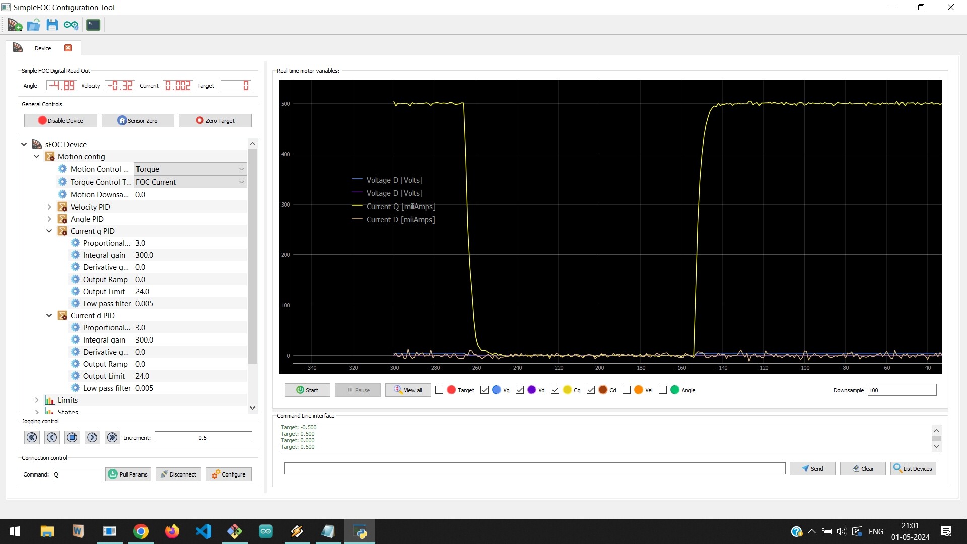
With the rotor held fixed, the current controller is able to regulate to the set point current since there is no back emf to contend with.
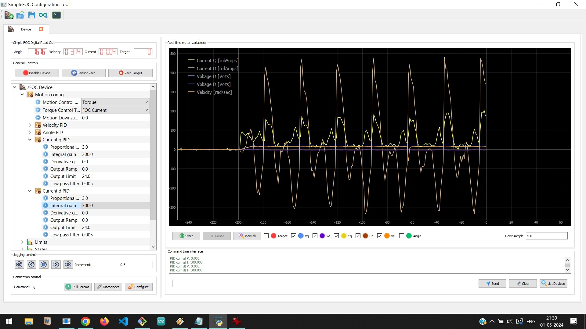
Basically, the q axis voltage quickly reaches the supply voltage, and the motor spins at constant speed, which matches with the Kv value. The q axis current is supposed to reach 500mA target, but it struggles due to the back emf, and it looks like the current controller has used the max supply voltage and is unable to overcome the back emf.
Is this expected? Does this indicate that the supply voltage has to be matched to the motor back emf so that the current is maintained in the presence of back emf? Am I missing something here.
I read about this in an application note when I was researching field weakening and this exact same behavior in my setup:
As the difference between the induced back-EMF and the supply voltage decreases, the phase current flow is limited, hence the currents id and iq cannot be controlled sufficiently. Further increase of speed would eventually result in back-EMF voltage equal to the limited stator voltage, which means a complete loss of current control.
Basically in foc torque mode, with no load on the rotor, the motor will spin as fast as possible (given the available bus voltage) where the backemf almost matches the phase currents, so you’re basically trying to control something with super small magnitudes.