At the First. I have done perfectly to " Step 3. Closed-loop control - torque using voltage"
I don’t know WHY THERE IS NO STEP4. or my chrome browser have some problem..?
Anyway.
Below code is for my “Step5” Section.
#include <Arduino.h>
#include <Wire.h>
#include <SimpleFOC.h>
#include <SoftwareSerial.h>
SoftwareSerial ext_port(PA3, PA2);
// BLDC motor & driver instance
BLDCMotor motor = BLDCMotor(5);
BLDCDriver3PWM driver = BLDCDriver3PWM(PA8, PA9, PA10, PB13, PB14, PB15);
#define DRV_EN PB5
// encoder instance
MagneticSensorI2C as5600 = MagneticSensorI2C(0x36, 12, 0x0E, 4);
// current sensor
InlineCurrentSense current_sense = InlineCurrentSense(0.009, 20.0, PA0, PA1, PA4);
// instantiate the commander
Commander command = Commander(ext_port);
void doTarget(char* cmd) { command.scalar(&motor.target, cmd); }
void setup() {
pinMode(DRV_EN,OUTPUT);
digitalWrite(DRV_EN,HIGH);
Wire.setSDA(PB9);
Wire.setSCL(PB8);
Wire.begin();
// init magnetic sensor hardware
as5600.init(&Wire);
// link the motor to the sensor
motor.linkSensor(&as5600);
// driver config
// power supply voltage [V]
driver.voltage_power_supply = 48;
driver.init();
// link driver
motor.linkDriver(&driver);
// current sense init hardware
current_sense.init();
// link the current sense to the motor
motor.linkCurrentSense(¤t_sense);
// aligning voltage
motor.voltage_sensor_align = 4;
// set motion control loop to be used
motor.torque_controller = TorqueControlType::voltage;
motor.controller = MotionControlType::torque;
// add current limit
// motor.phase_resistance = 3.52 // [Ohm]
// motor.current_limit = 2; // [Amps] - if phase resistance defined
// use monitoring with serial
ext_port.begin(115200);
// comment out if not needed
motor.useMonitoring(ext_port);
// motor.monitor_downsampling = 100; // set downsampling can be even more > 100
motor.monitor_downsample = 100;
motor.monitor_variables = _MON_CURR_Q | _MON_CURR_D; // set monitoring of d and q currents
// initialize motor
motor.init();
// align sensor and start FOC
motor.initFOC();
// set the initial motor target
// motor.target = 0.2; // Amps - if phase resistance defined
motor.target = 2; // Volts
// add target command T
// command.add('T', doTarget, "target current"); // - if phase resistance defined
command.add('T', doTarget, "target voltage");
command.verbose = VerboseMode::nothing; // disable commander output to serial
ext_port.println(F("Motor ready."));
ext_port.println(F("Set the target using serial terminal:"));
_delay(1000);
}
void loop() {
// main FOC algorithm function
motor.loopFOC();
// Motion control function
motor.move();
// display the currents
motor.monitor();
// user communication
command.run();
}
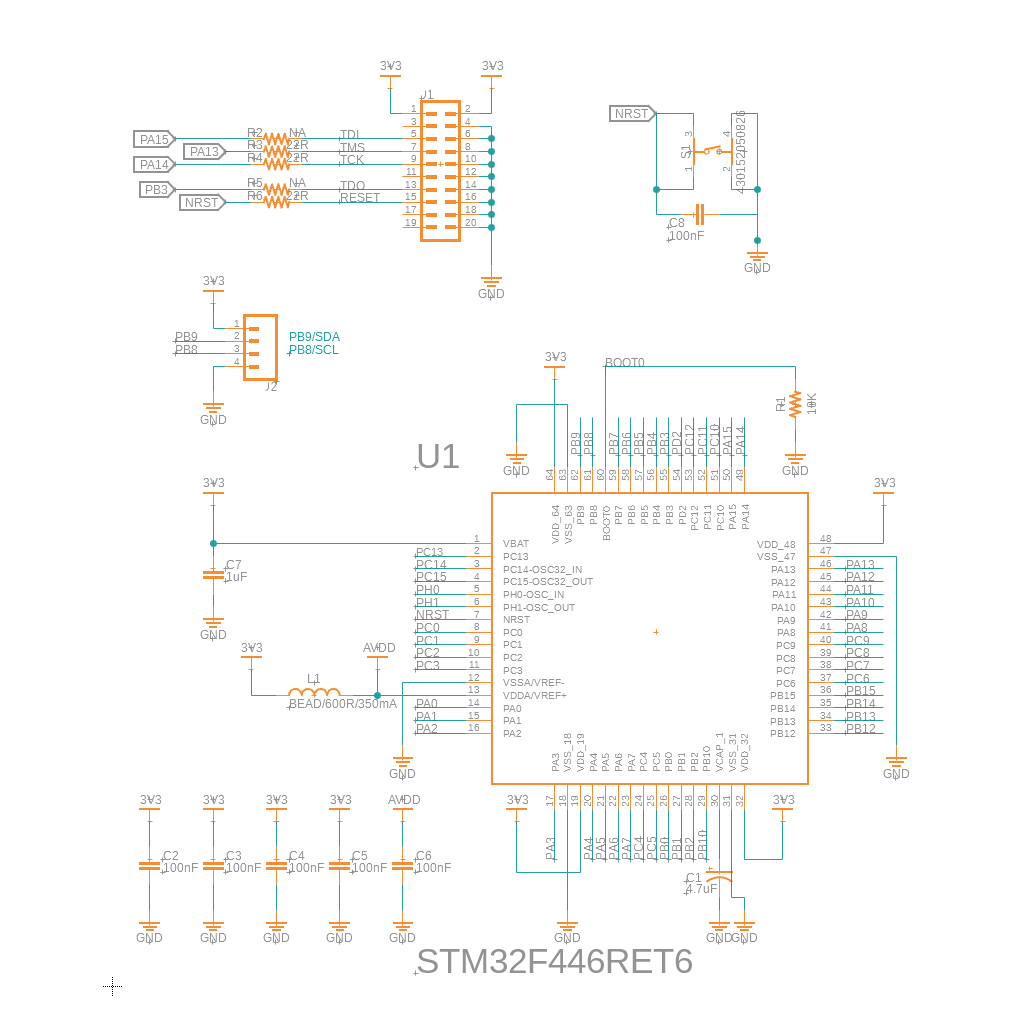
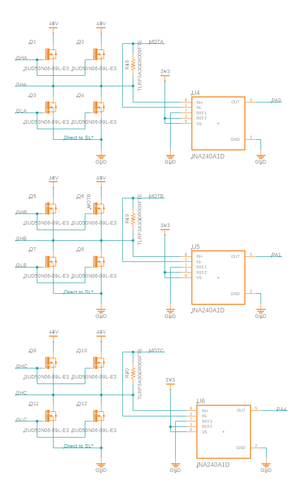
and this is from my own board schematics (MCU, Driver, Mosfets&CurrentSensor)

and it’s my Serial output that before d and q current.
MOT: Monitor enabled!
MOT: Init
MOT: Enable driver.
MOT: Align sensor.
MOT: sensor_direction==CW
MOT: PP check: OK!
MOT: Zero elec. angle: 2.24
MOT: Align current sense.
CUR: No driver linked!
MOT: Align error!
MOT: Init FOC failed.
and this is the result. very very very noisy.

I guess if the PCB board pattern can be the cause of the problem..?
It’s my board that highlighted current sensing lines.
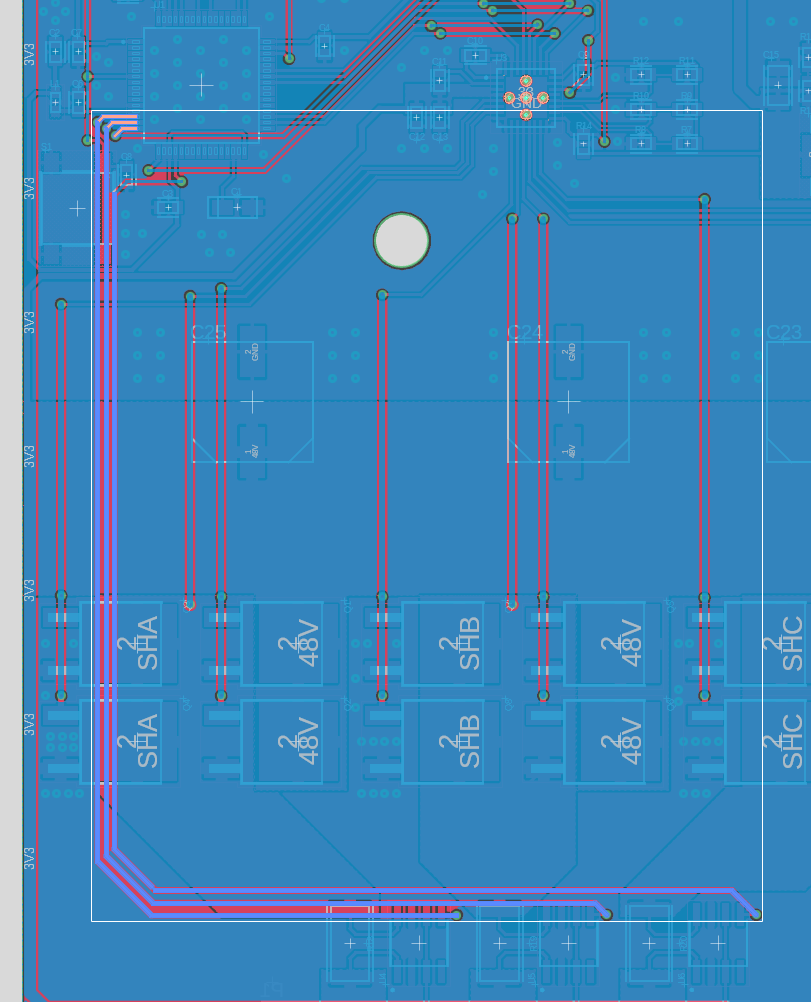
I think at first. there signals that through after sensing Amp(INA240A1) are have to no problem.
but can I know if there were similar problem at before?
I’m very thanks to your beautiful library.
I want to solve my problem with your help and give it somebody else who have problem that smilar with me.
I will wait. THANK YOU!!