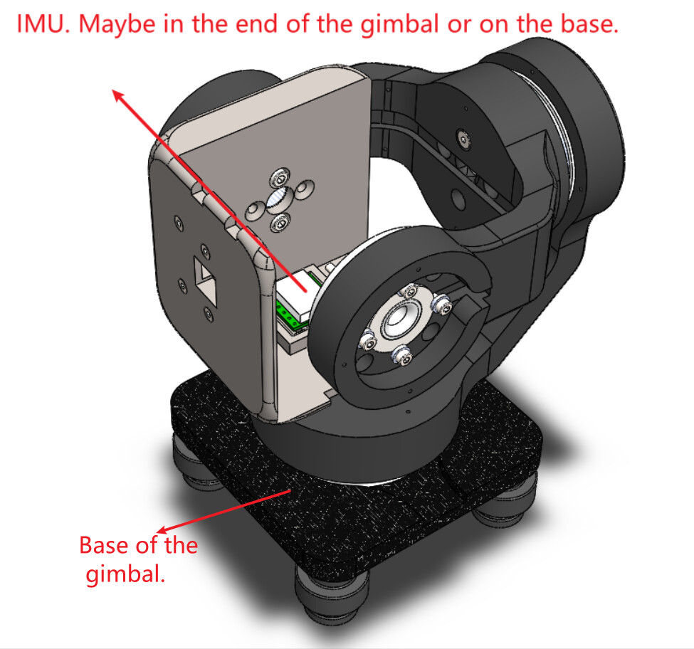
Hi, everybody! I want to make a three-axis brushless gimbal based on SimpleFOC. I want to write my own control code, and don’t want to use existing solutions, such as Storm32. My plan is that the motors of each axis are controlled by SimpleFOC (MCU - Arduino, magnetic encoder - AS5600). There is an IMU (MPU6050) that is responsible for calculating the angle. The main control MCU (blue pill) reads the data of the IMU and sends it to the three motors after calculation. I thought of some different solutions, I tried them all, but there are some problems.
Method 1: SimpleFOC works in angle mode. The IMU is placed on the base of the gimbal. It detects the angle change of the base. Then the blue pill sends these angle values to SimpleFOC through the serial port, so that the motor rotates in the opposite direction to offset the angle change. Trouble: The gimbal can be stable. But the response speed is relatively slow, which I cannot accept.
Method 2: SimpleFOC works in velocity mode. The IMU is placed at the end of the pan-tilt. It detects the angle change at the end. The blue pill obtains the target speed of the motor through PID calculation and sends it to SimpleFOC. Trouble: The gimbal can be stabilized, and the response speed has been improved, but it still cannot meet the requirements. And there is a problem with the shake of the motor.
Method 3: SimpleFOC works in voltage mode. The other operations are the same as mode 2, that is, the value calculated by the blue pill through PID is sent to SimpleFOC as the target voltage. Trouble: The motor is easy to oscillate and causes instability unless I reduce my PID parameters. But if I do this, the response speed of the gimbal will decrease.
So the above are some of my attempts. Unfortunately, none of them have achieved satisfactory results. Do you have any ideas?
Besides, his is my design drawing.I’m sorry that the blue pill is not shown in the picture, it may be connected outside.
I would be interested to hear people’s thoughts on this! It’s interesting to discuss the actual application as well the the details of the motor driving.
Personally, I would put the IMU at the end of the gimbal, near the camera, but actually that’s a good question! It might be best to have both, in the end version.
If you did not already do this, then before introducing the IMU, I would make sure that the gimbal works perfectly as a “remote control gimbal” (with no motion compensation). In this mode you can tune all the PIDs and make sure everything is stable and not oscillating or vibrating when holding a position.
Then add the IMU control to compensate the motion.
I think that the nice image produced by camera gimbals is at least partially due to the camera’s software stabilisation, so I think choosing the right camera and software is also important for the final result.
The AS5600 is not the most accurate sensor, you’ll probably have to smooth the output (increase the value of the velocity filter).
I think any of the control modes could be used, but I would have tried position mode first, and velocity mode next. Velocity mode (in my mind) would be more directly compensating the motion, but I have the feeling that the velocity (as a calculated quantity of the sensor output, involving time) is less stable than the position.
Thank you for your prompt reply!
At present, I am only experimenting with one axis motor, so I can try many schemes. I will consider your suggestions, and if there is any progress later, I will reply again.
Very cool project! You might be the first SimpleFOC-powered gimbal.
What makes more sense to me is to use the SimpleFOC board in voltage mode and calculate the desired voltage value that is to be applied in an external control loop. Do you have a PID in your blue pill?
I also don’t understand why the response with position control would be slower. Do you also have a PID in your blue pill for this? if you’re using only a P controller I can see why it’s slow but if you use a PID it can be much better. It might also be that the gain you have on the SimpleFOC controller are small and thus you obtain a slow response.
When SimpleFOC is in position control mode, I did not use PID in the blue pill. I just send the angle from the IMU to SimpleFOC as the target angle of the motor.
I have observed that the angle change of the motor is very small each time, maybe a few degrees. When in position mode, the small target angle causes the motor’s response to be insensitive. Maybe my thinking is wrong?
How are you calculating the desired angle? if you’re doing something that calculates the angle by checking the difference form where you are and where you want to be you have a P controller with unitary gain. You could totally try to implement a PID on the blue pill and the output of that PID be the input of the position controller on the SimpleFOC board.
Yes. I am using a P controller with unitary gain as you said. I have not tried to use PID to get the target angle on the blue pill. I will try it later.
We’ll probably need a bit more details to help you more specifically with your setup.
Can you tell us if you have already tuned your PID parameters or are you using the default ones?
You should definitely spend some time on this and find the parameters that suite your application the best.
Now in terms of control architecture, I agree that the simplest one to start with would be simplefoc in angle mode and IMU setting the target values. Just make sure you tune your velocity and angle PIDs well.
The velocity control with simplefoc and angle PID using the IMU values is a good option as well and should give you a bit smoother operation. But this all depends how well did you tune your parameters.
Now in terms of smoothness, I’m not sure if you’ll be able to get really smooth operation using the AS5600. Their resolution is not really good and even though the angle measurement is good enough to do FOC when you calculate the velocity from it it becomes very noisy and can introduce some osculations both because of the noise itself and due to the heavy filtering you need to put.
So what I would suggest you as a control structure would be:
use the simplefoc in voltage mode.
close the velocity loop using your gyro, which will give you a superbly smooth velocity measurement.
close the angle/position loop using the fused IMU data
You would still have the same amount of PIDs to tune but at least you would be using the most out of your setup.
I have tried several sets of PID parameters. I input the target angle in the serial port, and SimpleFOC can quickly reach the target position. But when I joined the blue pill to control the gimbal, the rotation of the motor could not keep up with the movement speed of the gimbal. This makes it look very lagging.
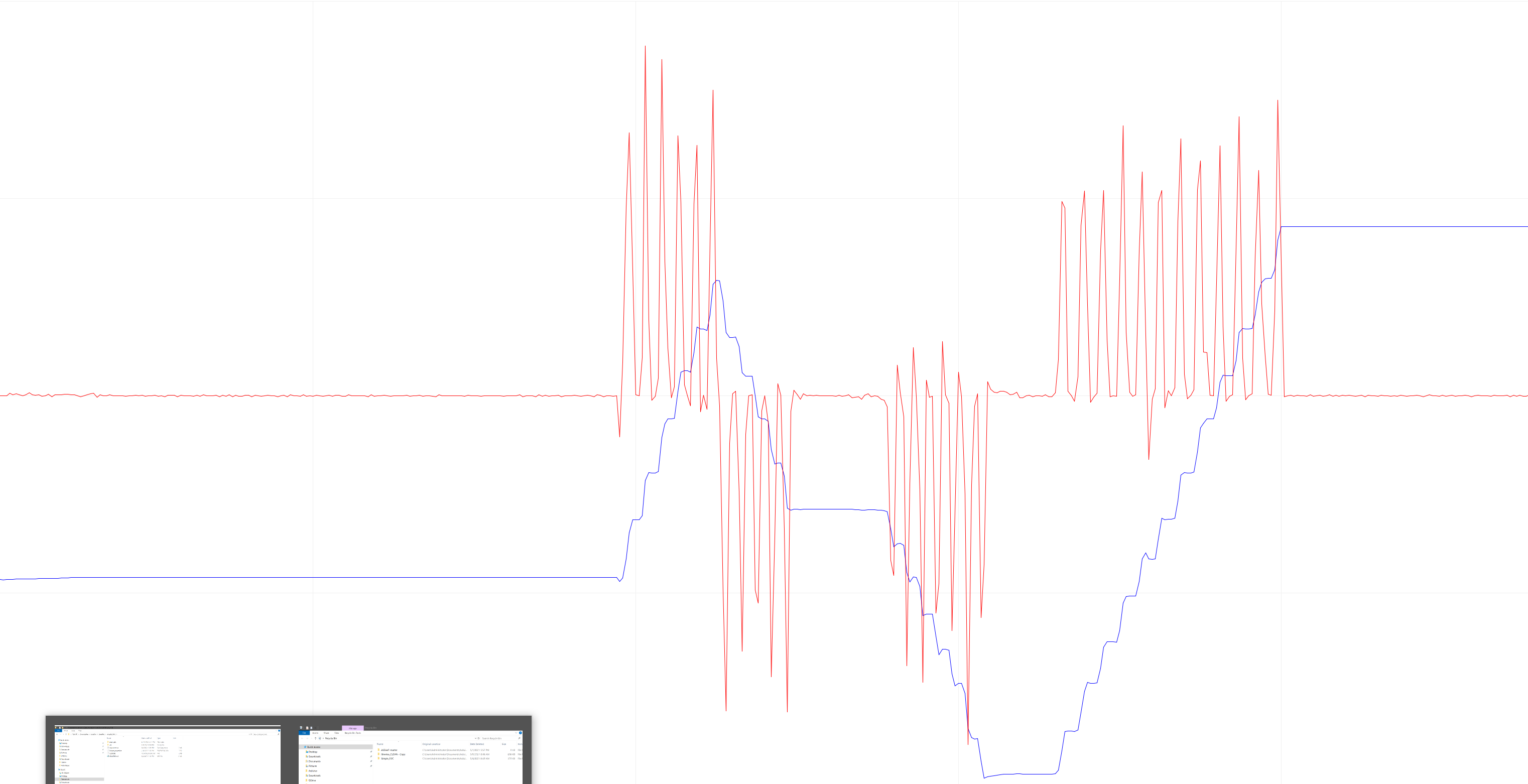
In addition, in order to improve the accuracy, I tried to use the 14-bit AS5048A magnetic encoder. I run the example code of magnetic_sensor_spi_example. It uses
Serial.println(sensor.getVelocity())
to get the speed.But I found that the speed noise is relatively large, and I don’t know if this is normal. It looks like this:
Your suggestion of using the angular velocity data of the gyro as the speed feedback of the motor is great! But I have some problems. The gyro measures the angular velocity relative to its own coordinate system, not the speed of the motor. I don’t know if it is right that the gimbal is usually in a horizontal position, so the coordinate axis of the IMU and the axis of the gimbal are parallel at this time, so the angular velocity of the gyro can approximately replace the speed of the motor?
No it’s not. I am using 5047P which is relatively close to the 58. Perhaps I am saying the obvious, but your setup needs to be fully grounded and all cables shielded. All shields go to real ground (bury a metal bucket in your yard, draw a multi-stranded cable to your work-bench and connect to a grounding bar. Also use mu-metal to shield the magnetic sensor if you have a noisy environment or large motors or magnetically noisy motors. Mu-metal motor housing too. Ground everything, wear antistatic gloves. Avoid plastic. Keep signal cables short and avoid power supply for powering your setup (50Hz or 60Hz leaks from power network). Use batteries instead. Use ferrite rings. I am working from home due to covid and this is my clean sensor signal:
May I ask, how does the bluepill talk to the motor controllers? Have you checked the speed of this control loop? If this communication is taking too long it could be part of the reason why the reaction time is slow…
One way to check could be to plot IMU signals and motor board sensors at the same time (I guess some custom program would be needed for this, to combine the data from 2 serial ports) and see what the lag is.
I have used shielded cables and connected the shields to the ground of my SimpleFOC. I am using battery power. But I have never got a signal as clean as yours.
Blue pill uses a serial port with 115200 baud rate to communicate with SimpleFOC. For example, simpleFOC works in position mode. This is my SimpleFOC command acceptance code:
void serialReceiveUserCommand() {
  static String received_chars;
  while (Serial.available()) {
    char inChar = (char)Serial.read();
    if (inChar == ',') {
      target_angle = received_chars.toFloat();
      received_chars = "";
    }
    else if (inChar != Motor_No)   //check the target of this motor
    {
      received_chars += inChar;
    }
  }
}
Blue pill uses the serial port to send target commands according to the above protocol.
I have not checked the time taken for communication, I will try it later.
I use a simple way to test the time cost of serial communication. I added a part to change the IO level in the serial port receiving code in SimpleFOC. Then I use my mini oscilloscope to detect the high-level time to judge the time consumption of my serial port.
But something strange happened. The serial port time is basically stable at two values, they are about 200us and 2.5ms. I use a computer to send P10.1234, through the serial port. No matter if I send it every 5ms or every 2s, the serial port time of SimpleFOC is always jumping between these two values. I think 200us is normal. 2.5ms should be the cycle time including FOC. But I don’t understand why this happens.
In addition, this is the oscilloscope video I got when I used the computer to send data every 5ms:
This is the oscilloscope video I got when I used the computer to send data every 0.5s:
And this is my test code:
void loop() {
  motor.loopFOC();
  motor.move(target_angle);
  serialReceiveUserCommand();
}

void serialReceiveUserCommand() {
  static String received_chars;
  while (Serial.available()) {
    char inChar = (char)Serial.read();
    if (inChar == ',') {
      target_angle = received_chars.toFloat();
      received_chars = "";
      digitalWrite(TEST_PIN,LOW);   // Received the end of the frame, pull down the IO
    }
    else if (inChar == 'P')
    {
      digitalWrite(TEST_PIN,HIGH);  // Received frame header, pull up IO
    }
    else if (inChar != 'P')
    {
      received_chars += inChar;
    }
  }
}
I think this is ok. Judging by your code, sometimes the command sends within one call to serialReceiveUserCommand(), and sometimes the command takes 2 (or more?) calls to the serialReceiveUserCommand() to be received completely. But in between the FOC loop is executing, so that is ok.
So from the point of view of the serial communication on the motor board side, I think this is ok. 200us is acceptable, and 1 loop delay to receiving the command is also ok, I think.
I think the total loop time on the motor board of 2.5ms is quite high. This means FOC is executing at 400Hz - I think this is a little on the slow side. On the other hand, gimbal motors don’t need to spin fast.
On the sending side, on the bluepill, I guess you are sending to one motor after the other. So 2.5ms communication time per motor would mean 5ms between motor 1 and motor 3 receiving their commands.
At this point I have to say I don’t have the experience to judge it - it sounds like a slightly difficult setup to manage - AS5600 is slow and somewhat inaccurate, Bluepill has to read the IMU and then command one motor after another via serial, which does not have fixed timings.
There are some people on the forum who have made working balance bots - perhaps they can say something about these timings in relation to IMU control.
Today I learned that the lower 3 bits of the AS5048A(AS5047P) magnetic sensor’s register data are not accurate. In other words, the data it reads from a stationary magnetic field may jump within the range of 2^3 =8. Then if the angle data is read every 1ms, the velocity error caused by this jitter is calculated like this:
The code I used to read the angle and speed of the encoder is here:
I once heard two people talk about it. One of them was in this post in this community. They said it was the ADC sampling accuracy. I don’t have specific reference materials either. Sorry.
That is untrue. There is no evidence of such claim. Unless you find out the exact ADC and CORDIC MCU silicon reference as well as the CORDIC ADC/DSP algorithm implementation microcode used in calculating the angle from the four hall sensor coordinates, and have the knowledge to take it apart and critique its merits, this blanket claim is baseless.
This is unfortunate however short of me walking into your place and examining the setup and waving an EMF meter, it’s impossible to offer suggestions. This 5048A/B sensor is designed for the robotic and automotive industry, it can withstand a pretty noisy environment, there’s got to be a pretty obvious source for the noise. Did you also use true ground (literally a buried bucked in the backyard)?
Something very important, I am using 5047P which is the extra-high speed version which uses a different CORDIC system and angle timing deviation error correction algorithm so by the time the signal hits the SPI bus it’s already corrected, and you are using the slow speed 5048A. However such high error you showed cannot be explained away by systemic noise.
Perhaps you acquire a 5047P and re-setup your system? I am not sure. Wish I could help.
Edit: Perhaps a stupid suggestion on my part but you could check the value of the error register of the sensor to see if your magnet is correctly set up? May be your magnet is right or not set up correctly?
> ...register address x3FFD (AS5048A) : •OCF (Offset Compensation Finished), logic high indicates the finished Offset Compensation Algorithm. After power up the flag remains always to logic high. •COF (CORDIC Overflow), logic high indicates an out of range error in the CORDIC part. When this bit is set, the angle and magnitude data is invalid. The absolute output maintains the last valid angular value. • COMP low, indicates a high magnetic field. It is recommended to monitor in addition the magnitude value. • COMP high, indicated a weak magnetic field. It is recommended to monitor the magnitude value.
You are right. I cannot say that until there are documents to prove it. And unfortunately, I searched for related documents today but couldn’t find it either.
This is the result I got when I used Keil MDK to program STM32 to read the angle data of AS5048A. It can be seen that the angle data has very little jitter. I don’t understand whether this is a normal phenomenon of the sensor or is caused by noise.
In addition, since my gimbal needs to be moved around, I cannot connect it to the real ground.