Perhaps you already know that I do not have practical experience with the SimpleFOC software nor BLDC drives. But I do have a fair amount of experience with power electronics and motor drives in general. I hope my comments here do not become too irrelevant for you.
I am surprised to learn that the measured motor current is being filtered by the software with a time constant of 5ms, before it is used in the current control loop. It seems odd to me. Are you sure this is correct?
If you do that, then of course you cannot have a responsive current control loop. Why should it be necessary to filter the current signal? Is the sampling of the current signal not syncronized to the switching of the power transistors? Otherwise, I can believe that the power switching transients are disturbing the current measurements. I know that I was commenting about this issue in this other thread regarding a driver for stepper motors:
https://community.simplefoc.com/t/low-side-current-sensing-for-stepper-motors/7235/39
I can imagine the need to filter the speed signal with a time constant of 5 ms, but again I think it will cause severe problems for a fast speed control loop. I know that a small, brushed DC-motor used as tachogenerator can provide a speed signal with much less noise. If have used it for sewing machines, and with two amplifications of the analog value to provide a wider dynamic speed range. But a brushed DC-motor don’t provide a shaft angle that is needed for FOC.
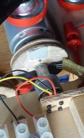
I have been considering a small BLDC-motor could be used to provide an angle and speed signal and again with two amplifications to increase dynamic range. I have tried to look at the EMF-signals from such a motor with one terminal at a fixed center voltage and then you sample the signal from the two other terminals. This is the test set up:
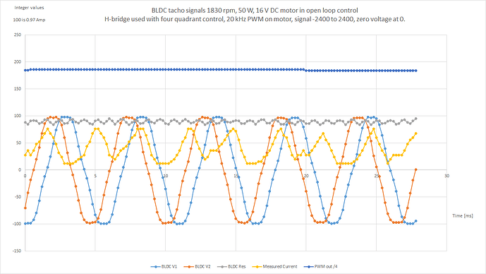
This is the result:
The BLDC generator got 12 poles and got Kv=4300. It is rotated at a speed of 1830 rpm. It then makes an electrical frequency here of 183 Hz.
Provided that you have two sine waves 60 degrees apart, you can calculate the peak value of the current sine wave to be:
EMF peak = 2* sqrt( (v1^2 + v2^2 – v1*v2) / 3).
Gray curve = sqrt(V1^2 + V2^2 – V1*V2).
The gray curve got some ripple, and I think it is mainly caused by the measured voltages from the BLDC generator deviating from being sine waves. But it is a fair signal and with a relatively high ripple frequency.
Using this motor, I find it possible to get a noise in speed signal below 0.05 rpm and you should be able to track a reasonable shaft angle at speeds below 0.5 rpm. You got a risk that you can lose track of angle by very low speeds, but I guess that you may have some counter measures by providing a small ping signal to the main motor causing a small movement now and then to ensure that you keep track of the angle. Otherwise, you will need some recalibration. You will need two consecutive measurements to get information on speed directions.

