How do you improve slow speed control?

I like you to study this video, with a comparison of three BLDC motor drives. At low speed, they all got a a jerky motor rotation movement. Why is that so?

I guess, that they all use an angular hall-magnetic sensor to measure the angle of the rotor. I furthermore guess, that this angular sensor is more accurate, so that in itself should not cause this jerky movement.

At 7:09 in the video, it is explained, that the O-drive perform an initial calibration, which includes a slow speed. But this movement is not jerky.

Have you tried something similar with the FOC software and some controllers? Can you make the motor go slow without a jerky movement, like you see in the video?

I am interested in the problems involved with slow speed control of electrical motors, and how it can be improved.

That kind of steppy motion is natural for velocity control on a motor with significant cogging torque. You may be able to reduce it some by increasing the PID gains so the velocity controller responds more quickly to the variation caused by cogging, but it may just become unstable instead.

What I would do is use the angle_nocascade mode. The cascaded style performs better with inertial loads, but if you have another layer of control on top, it can give smoother and more precise positioning. Like for CNC machines, the controller generates acceleration ramps so inertia is already accounted for.

If you need smooth velocity control at low speed, increment the target angle similarly to how velocity_openloop does it. Two caveats:

  1. Stop incrementing the target if it gets some distance beyond the measured angle, to prevent windup if the motor is stalled.
  2. Add a way to wrap the angle back when it gets large due to the limited numerical accuracy of floating point.

I would like to know what the ODrive is doing to get smooth calibration motion. Thankfully the v3.6 is open source, so I may go digging to find out…

Thanks for your reply.

I think some of the comments to the video on YouTube is interesting as well. @boobelan is suggesting, that the ODrive use a higher current in open loop drive during calibration and therefore the cogging moments becomes relatively smaller.

I agree, that higher gains in the position and velocity control loops should decrease this jacking caused by cogging. One way to have higher gain is to increase the control loop sampling and update frequency.

I got a suggestion too. I guess you use the encoder to output an angle for your controller. But part of that is that there is a bit of noise on this angle. You also need a speed signal to the controller, which calculated by subtracting the previous measured angle a short time before (depending of control loop frequency). When you do this differentiation of the angle signal, the speed signal will have significant noise. It is increased by higher control loop update frequecy. When you have the encoders own measurement cycle unsynchronized to the motor control loop, you get errors or noise from that too.

Update frequency limits your top speed, but sensor noise (encoder and current sensors) is usually the limiting factor for how fast the PIDs can respond to changes.

The Sensor class has a variable min_elapsed_time to limit how often the velocity gets recalculated (default 1 millisecond) to reduce the effect of angle noise. Then velocity gets lowpass filtered by the motor class, which further reduces noise but also reduces how quickly the PID can respond to changes in speed. The default time constant is 5 milliseconds. Then the current sense is also lowpass filtered with default 5ms, which I think means there will be a 10ms delay between measuring the speed and applying torque in response. There’s an optional lowpass for the angle too, but it’s disabled by default.

The defaults are chosen to give decent results for beginners on a variety of hardware, not for maximum performance. With good hardware, you can use lower filter constants.

Antun did some testing of INA240 versus AS712 a while back, and got much better results with the INA240. And presumably that was taking one sample per update, so it should be even better with oversampling. Maybe good enough to eliminate the need for lowpass filtering entirely on the current. Of course the shunts would need to be much lower resistance for high current motors, but should be able to get the same precision proportional to the overall range.

Another thing that’s been on my agenda for a long time is to combine the voltage-based current control with hardware current sense. I think that would be considered feed-forward. Predict the necessary voltage so it responds faster, but use measurement and PID to correct the error so it doesn’t explode if you guess wrong.

Perhaps you already know that I do not have practical experience with the SimpleFOC software nor BLDC drives. But I do have a fair amount of experience with power electronics and motor drives in general. I hope my comments here do not become too irrelevant for you.

I am surprised to learn that the measured motor current is being filtered by the software with a time constant of 5ms, before it is used in the current control loop. It seems odd to me. Are you sure this is correct?

If you do that, then of course you cannot have a responsive current control loop. Why should it be necessary to filter the current signal? Is the sampling of the current signal not syncronized to the switching of the power transistors? Otherwise, I can believe that the power switching transients are disturbing the current measurements. I know that I was commenting about this issue in this other thread regarding a driver for stepper motors:

https://community.simplefoc.com/t/low-side-current-sensing-for-stepper-motors/7235/39

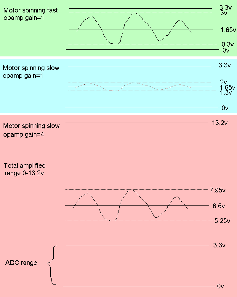
I can imagine the need to filter the speed signal with a time constant of 5 ms, but again I think it will cause severe problems for a fast speed control loop. I know that a small, brushed DC-motor used as tachogenerator can provide a speed signal with much less noise. If have used it for sewing machines, and with two amplifications of the analog value to provide a wider dynamic speed range. But a brushed DC-motor don’t provide a shaft angle that is needed for FOC.

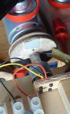
I have been considering a small BLDC-motor could be used to provide an angle and speed signal and again with two amplifications to increase dynamic range. I have tried to look at the EMF-signals from such a motor with one terminal at a fixed center voltage and then you sample the signal from the two other terminals. This is the test set up:
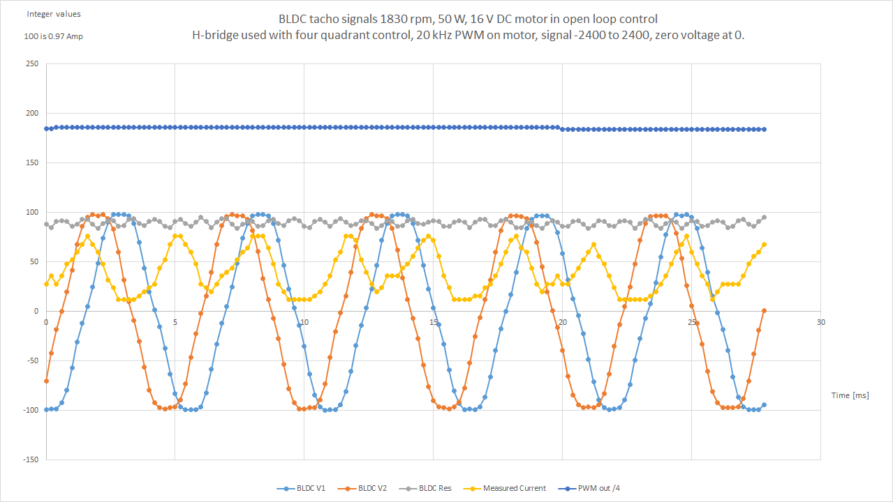
This is the result:

The BLDC generator got 12 poles and got Kv=4300. It is rotated at a speed of 1830 rpm. It then makes an electrical frequency here of 183 Hz.

Provided that you have two sine waves 60 degrees apart, you can calculate the peak value of the current sine wave to be:

EMF peak = 2* sqrt( (v1^2 + v2^2 – v1*v2) / 3).

Gray curve = sqrt(V1^2 + V2^2 – V1*V2).

The gray curve got some ripple, and I think it is mainly caused by the measured voltages from the BLDC generator deviating from being sine waves. But it is a fair signal and with a relatively high ripple frequency.

Using this motor, I find it possible to get a noise in speed signal below 0.05 rpm and you should be able to track a reasonable shaft angle at speeds below 0.5 rpm. You got a risk that you can lose track of angle by very low speeds, but I guess that you may have some counter measures by providing a small ping signal to the main motor causing a small movement now and then to ensure that you keep track of the angle. Otherwise, you will need some recalibration. You will need two consecutive measurements to get information on speed directions.

Specifically it is the d and q current that are filtered, not the raw sensor values.

So the transformation by rotor angle is done before filtering, meaning it should be able to follow the rotation without lag, but changes in amplitude will be slowed down, limiting how fast the velocity PID can get a response out of it. At least I think that will be the effect.

Sampling is typically synchronized with the transistors using the LowsideCurrentSense class. It works for inline sensors too, and is better optimized on STM32 which has a very slow implementation of analogRead used by the InlineCurrentSense class. But the inline class works on more platforms, because lowside typically requires a specialized ADC setup for each one, and some hardware can’t do it at all.

That said, it would be nice to make some specialized implementations of InlineCurrentSense too, which do oversampling to improve the accuracy since hall effect current sensors are usually quite noisy. In that case the sampling is not synchronized with the transistor switching, but hopefully any spikes from switching will get drowned out in the mix. It would also be possible to sample into a buffer and filter out spikes before averaging, although it would take more CPU time than using STM32’s hardware oversampling.

That is an interesting idea using a DC motor as a speed sensor. If you need really precise velocity control, you could use that in addition to a position sensor. Or perhaps with the flux observer so all you need is current sensors and the DC motor velocity sensor.

On your BLDC signal image, the gray line has 6 ripples per cycle of the sine waves, so I think those are the cogging steps. The winding calculator gives 36 steps for 12 poles, so 6 per pole pair.

Benjamin Vedder’s VESC firmware uses a technique called HFI (high-frequency injection) to keep track of the angle at low speed by sending a ping signal, but it hasn’t been implemented in SimpleFOC yet.