Here’s my attempt so far:
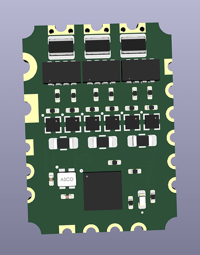
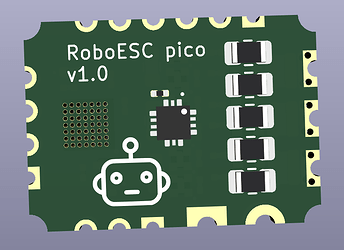
It’s a 12.5 x 17.5mm BLDC controller with on-board MCU and sensor, for mounting on a motor.
- Should work for 4.5-18V, max 1-2A
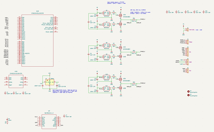
- STM32G431 MCU
- MA782 sensor
- Current sensing via MCU’s built-in opamps
- USB/Serial, CAN, I2C, SWD (all TTL, just the MCU pins, transceivers etc to be supplied externally)
- Needs separate input of 3.3V for MCU/logic
There are a number of things that still need to be worked out, and I have not routed it yet (although it looks like it may be possible  )!
)!
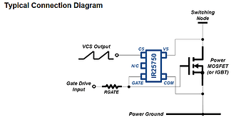
The MOSFETs used have to be P-Channel/N-Channel types, P-Channel for the high side. The concept is to use the tiny MIC4414/MIC4415 low-side FET drivers to drive both sides of the MOSFETs. The 4415 (inverted input) drives the P-Channel. The VGS rating of the FET limits the max supply voltage permissible so the supply voltage can be used directly to switch the FETs.
One of the things I’m unsure of is whether I can use the N-Channel driver IC to drive a P-Channel FET in this way, but so far I have not discovered a reason why not…
For the current sensing, I currently have an inline configuration, but I’m not sure it will be easy to bring the common mode into the MCU’s range (only VSSA to VDDA  ). So I think I’ll have to change it to a low-side sensing configuration, which will make the routing more difficult. If anyone has any ideas for how to handle the common mode issue, I’d be intested to learn!
For the board size, I think I will have to make it a little larger to make the phase pads easier to solder… also, I know that it can’t be produced as pictured, with castellations on all sides… the plan here is to add a removable “daughter-board” with the USB and SWD ports so it is easy to program it initially. Then, once programmed it can be cut away from the daughter-board to make it tiny-small. 
I think I might make it a little longer, and use some 3x3mm FETs which should bring the power up quite a bit. The current FETs are small, but not ideal. As it stands it would be better to use a small driver IC than the discrete FETs, so that should be improved.
Note that this design will not be cheap to produce. It will need tiny vias, probably will need blind vias, has a BGA MCU and will need at least 4 layers, maybe 6… so I am not sure I will really complete and produce it as is.
Feedback is welcome!


