I started off with the goal of replacing the controller for my (supposedly) 1000W Lathe motor. The current controller runs with hall sensors and is very jerky at low speeds. There is little hope of tuning the existing controller. I was able to run a prototype with simpleFOC on my bench with a small motor, STM32 board with current sensing. I got a DRV8302 driver board with the intent to drive the larger motor. Now when I started trying to reverse engineer the Lathe controller (yes, I should have done this first!) to get some specs and re-use the existing motor power supply, it seems it runs at +/-150V or so when I probed the 6 drive transistors. This is far higher than the DRV8302 is capable of, so I will need a new board. I would like to learn a bit about how the voltage is chosen for a BLDC motor, but I seem to find little literature. The resistance between any two of the 3 pins is about 6ohms (so 3ohms per coil?). Can someone point me in the right direction?
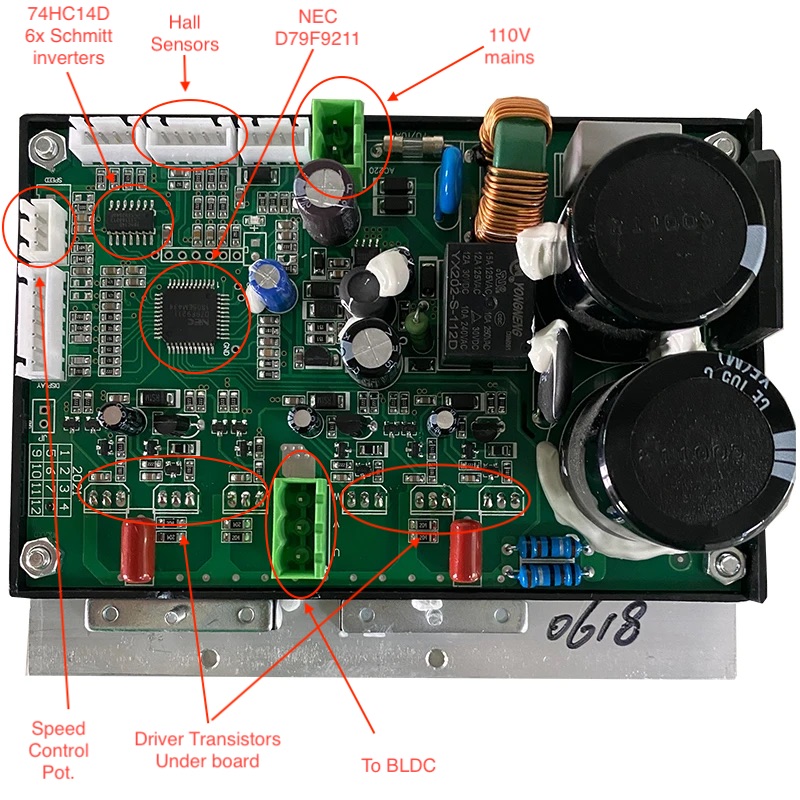
One last ditch effort is for me to find the pins driving PWM off the original controller (NEC D79F9211) and bypass those with STM32 SimpleFOC outputs. Attached a picture of the generic controller which can be found for purchase, though those sites warn that I am better off purchasing the motor and controller together as the programming is specific to the motor.
Say you have a motor for 100V and the wire in the coils goes around the stator 100 times. Then you could cut the winding in two parts and put the two 50 turn parts in parallel. You now have a motor for twice the Amps and 50V.
You could also buy thinner wire, about half the copper cross section and wind 200 turns on each part of the stator. You now have a motor for 200V and half the amps…
So for example for a gimbal motor, the RPM never needs to be more than say 10RPM. So it doesn’t matter that you would need a 3600V for 3000 RPM. So they aim for 10RPM at 12V, which gives the lowest current-per-torque figure possible for that motor.
There are some disadvantages to a low voltage, high current motor: The wires from powersource (bateries) to the controller and from the controller to the motor need to be bigger.
So for a lathe I’d expect them to just rectify and smoothen the line voltage to get about 160V, and then use that. (I’m guessing you’re in north america where line voltage is about 115V. In europe the motor would be configured for 320V as opposed to your 160V. The controller would then require higher voltage-capable mosfets, but only half the current).
Your question surrounding how to choose the voltage is an interesting one. Typically the voltage is chosen based on what supply is available. AC120, AC240, DC48. Once the supply is factored in, then the power (speed, torque) required can be factored, motor technology selected, then sizing equations can ensue.
Electrical safety regulations can play a role in what voltage you choose. Electrical safety is about risk of fire and people being exposed to electrical shock. It means risk of death and damage to property. If a product you are responsible for may have caused such things, insurance companies put layers on you, and they may not cover you. If you can keep the voltage at 24 V or below, the rules are not that severe and you got more room for experiments.
Thanks for sharing your thoughts! I suppose that the design above is focused a lot of cost savings, so I suspect thinner windings and lesser copper for the same torque? My thought of simply driving with a capable drv8302 and 48v supply may not be a good idea as I would need higher current for the same power output and the windings and/or heat dissipation would likely be lacking. Direct conversion of AC and savings on a complex power supply is very interesting, though the board above still seems to have inductors and safety capacitors suggesting a switching converter of some kind.
My argument about voltage being arbitrary is when you get to chose BEFORE the motor is built.
So when the requirements specify a 300W motor, you (ehh. the manufacturer) can chose 30A at 10V, 3A at 100V or 1A at 300V.
Once the motor is produced (i.e. the windings are in place), you have a certain RPM/V constant that the motor has.
Assuming you have a medium lathe with a 900W motor, they probably chose for 6A at 150V. As for the application a “max RPM” of say 1500 is acceptable, they will configure the motor for 1500 RPM at 150V: 10 RPM per Volt.
If you then go for 48V, the max RPM will simply be 48/150 * 1500 = about 480 RPM. The wires in the motor are able to withstand 6A without overheating. That hasn’t changed, so you can feed a max of about 6A * 48V = about 288W into the motor.
An alternative would be to take the motor apart, remove all the copper and replace it with thicker strands that can handle 18.75A. So then you can achieve the rated 900W at 18.75A and 48V. This is such an operation that I’d consider it “not worth the trouble”, but that’s what needs to be done if you really want it.
The capacitors are there to create a steady 150V from the 110V AC that comes in. As a simple circuit to do that (bridge recitifier) would cause big spikes in current on the incoming AC line, those AC current spikes need to be flattened a bit. So that’s why there is a filter in there.
If they have gone “all out” they even have a power factor correction circuit in there. Then they will also drawa current from the line when the voltage is NOT at the max. Honestly, I don’t think that’s the case here: That would require another big inductor besides the one for the filter and I don’t see that.
You say: “thinner wire, less copper”.
No: There is no such thing as a free lunch. The amount of power required dictates the general size of a motor. Then by choosing thin wire, lots of windings, you can get a high-voltage, low current motor. Or by choosing very thick wire, you get a low voltage, high current motor.
This is the theory, that assumes that you can cram the same amount of copper into the space for the windings. If the wire gets really thick, the edges where the stacking is sub-optimal start to matter. If the wire gets really thin, the extra space taken by the insulation layer starts to make a difference. But in between the person doing the windings can choose the thickness of the wire and more or less freely decide on the max current and thereby the voltage at which the motor will run at max RPM.
Yes, all of this is a hobby and while it is fun to learn new things, rewinding the motor is a step too far for me 300w might still be reasonable as I don’t do any heavy machining, but that depends on figuring out how much current it can tolerate.
The plan is to characterize the motor the best I can, like finding the number of poles, windings resistance, peak current with existing driver. And then hijack the microcontroller outputs and inputs to drive it separately. The lathe already has a high resolution quadrature encoder for the lead screw that I can use, and I should be able to add current sensors on the motor connector paths. So I don’t lose the lathe in the meantime, I am looking at the “ZM-7205A” which seems to have similar specs, with some ability to program parameters. Let’s see how it goes.
You are correct, I missed the part where the number of turns will be more with thinner wire. So then the simpler power supply may be the only reason for going down this path. On another note, would the insulation ratings of winding wire be in the kilovolt range typically? I was wondering if I can test a modified driver on the bench with a smaller low voltage high current motor since I do not have two of the lathe motors to experiment. Hopefully the lower current should atleast provide enough torque to overcome stiction at start.
You measured the “150V DC” right? Then from the power rating on the “motor rating plate” on the motor, or on the whole lathe. If there isn’t a power rating, there will be a current rating. Multiply that by 0.7 and you have the theoretical “max current” at 1.41 times the voltage.
What can’t be changed is that if they intended the lathe to do 1500 RPM originally, I think it will be very annoying to have to run it at max 500RPM.
(All my calculations assume 100% efficiency and no conversion losses. Correcting for those is also possible, but “out of scope” for a quick back-of-the-envelope calculation).