Thanks for the SimpleFOC project, and looking to use it in a project on developing a gimbal using the SimpleFOC sheild and library. The main requirements are as follows :
Operating manner is of a gimbal - high torque and low speed. So the motor is basically operating around the stall condition on the speed-torque curve.
Torque requirement > 1.5 Nm
Direct drive
Supply voltage is upto 24V
I am currently looking at a couple of motors, and need some help with checking my numbers.
Resistance = 5.5 ohm. Assuming this is line resistance, phase resistance is 2.75 ohm. For use with the SimpleFOC shield, we need to have supply voltage approx 12V to not go near 5A driver limit.
Since the motor will be near zero speed, the operating current is close to stall current, which is 12V/2.75 ~ 4.36A. Torque produced at this current is = 4.36A * 0.39 Nm/A = 1.7 Nm.
The first motor spec says max torque is 8.3kg.cm and the second motor says 6000-9000g.cm (i.e 6-9kg.cm). Converting that to Nm give about 0.8Nm for both. So both under your 1.5Nm requirement, I think.
What are you trying to do with them? A 2 axis gimbal for a camera? What weight?
Hi Owen, yes a 2 axis gimbal for a camera payload. The payload weighs 2 Kg. The idea is to stabilize the camera using a gyro as a sensor and commanding the SimpleFOCShield over I2C.
For the first motor, the 8.3kgcm is at 15V and 1.5A, but my guess was we should be able to get higher torque at higher current, with the limitation coming from the 5A of the FOCShield. The same logic is applied for the second motor too. Do you see a problem here?
You will have to deal with higher temperatures, when you raise the current. Maybe to a point, where it leads to failure.
My other remark is more like a question:
Do you really need 1.5Nm when you place the cameras CenterOfGravity nearest to the gimbals pivot points.
Sure you still have to deal with the inertia caused by the camera mass, but you don’t have to lift it…
@o_lampe and @runger Agree with the balancing part. The gimbal axes have been placed to pass through the center of mass, so the majority of the torque required from the motor will go into actually moving the camera.
As for the 1.5Nm requirement, that was given and I suspect there is some margin on that, so something around 1Nm should also probably work.
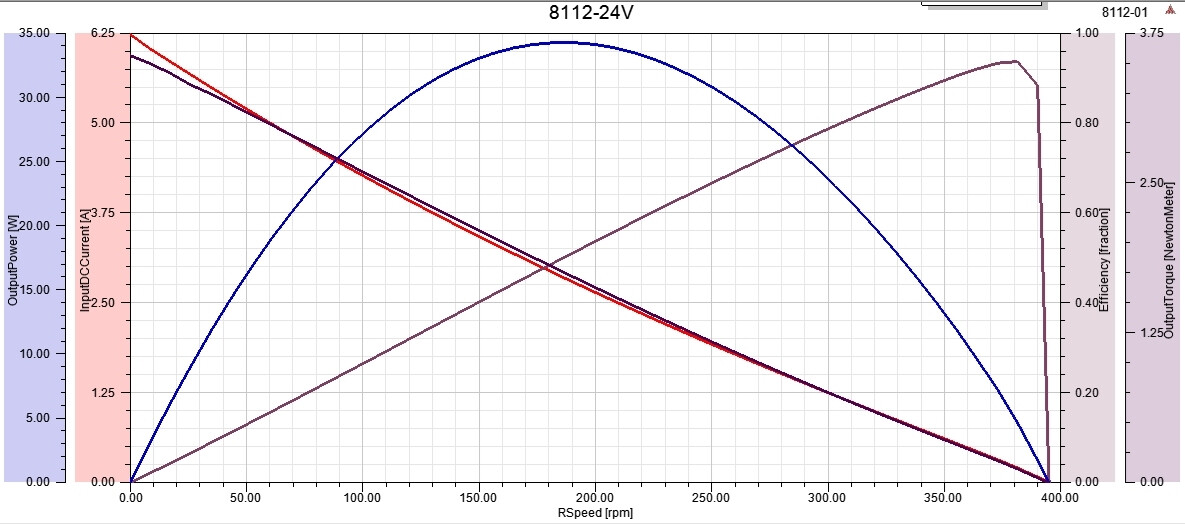
The nominal operating condition stated is at 2A and 20V producing torque around 0.8 Nm. The speed torque curve for this motor at 24V obtained from the vendor is given below. For a 2A current, the motor has approx 250 RPM speed and produces approx 1.2 Nm of torque. My question is, since gimbals are operating at really low speeds, it this the relevant operating condition to consider? Is not the operating regime more closer to 0 RPM near the stall torque?
The diagram shows the motor running without any current limitation. But in sFOC we set limits.
In your example, setting the limit to 2A , the motor would produce 1.2Nm from standstill.
Got it. Does that also imply that for a gimbal type operation where the amplitude of movement is small but at a high frequency, the torque being produced will be approx 1.2Nm?
Ok, in that case, given the speed-torque at a particular voltage, can we consider the operating point to be close to the 0 RPM condition? ie close to the stall torque, and hence stall current condition?
I’m not entirely sure what you mean, but we are talking about a current-limitted scenario.
That means we are probably running at much lower current than stall-current would be in an unlimitted scenario. Any given figures regarding stall aren’t relevant anymore.
I think I might be missing something here. I am trying to reason based on a simple DC motor analogy. When we provide voltage across the leads, at that instant, the windings are resistance only and this generates the initial current spike, which produces a large initial torque. As the speed increases, the back-emf eats into the supply voltage so that there is lesser and lesser current in the windings as the speed increases and in the absence of any other external torque, the speed will settle to a value where the back-emf and the applied voltage are equal. This is the highest speed at which the motor will turn and is the no load speed. At this condition, the current is zero except for the that required to overcome any friction.
The highest current in this whole process occurs just when the motor starts and is similar to a stall condition in the sense that the rotor has close to 0 RPM. Hence, I was interpreting the initial current to be the stall current, and this condition to be the operating condition for a gimbal.
I haven’t considererd any current limiting here. Do you see anything I might be missing?
That’s a pretty good description, but in sFOC world you wouldn’t have an initial current spike.
The curent is limitted like a stepper motor setup. Think of holding-torque instead of stall-torque.
I would suggest a large stepper motor with tmc2209 driver, they give very smooth motion and the coolstep thing helps a lot although I was never able to get their driver working to use it, it’s theoretically sound.
1.5 Nm is a lot of torque or a gimbal motor, that would be a larger motor, not a smaller one. Stepper motors give a lot more torque per unit current than any gimbal motor. In any case you could use a stepper with SimpleFOC but there is little need for that either.
FOC is best suited to higher rpm applications which need higher energy efficiency, it works any time but that’s where it shines.
You can’t use anywhere near that current with that motor you are hoping to use because it will overheat. I use similar sized motors and they can’t handle more than about 400 mA of current if they are standing still.
The current and power ratings are higher for a motor when it’s actually producing power because a lot of the energy comes out as mechanical power. If it’s not moving, it’s all waste heat!
Ok, I am a bit confused here. The holding torque is due to current limiting to a lesser value than the stall current?
Just to come back to my original question, what I am trying to do is see how much torque will be produced when the motor’s average RPM is essentially zero. In the absence of current limiting, this will be close to stall current. With a current limit set in sFOC however, the torque will be close to whatever the limiting current will produce depending on the torque constant. Is this a correct interpretation of what you’re trying to say?
We tried stepper motor, and get the positioning resolution we would like (10 milli-deg or less) with micro-stepping. However, the torque we managed to get when microstepping was not good enough. Plus it seems harder to do full closed loop control with an IMU and stepper than with a BLDC motor.
I wonder if that’s only an urban legend?
I’ve replaced a NEMA14 pancake stepper with a similar sized BLDC 2805 gimbal motor on my 3D-printer extruder and I could extrude much faster with the gimbal motor (using sFOC with step-dir interface)
I can’t provide real current numbers for the BLDC, but it didn’t get hotter than the stepper.
Well I see some nema 23 here that say 3Nm for 2A, I suppose it’s possible you could get more from a gimbal, but stepper motors have the windings on the outside connected to the massive metal case so they are much more capable of dissipating the waste heat.
From the fundamentals, the amount of magnetic flux you get per watt is fixed by the conductivity of the wire, I think. Hence, if it’s superconducting you can have quite a magnet. The torque would be the magnetic field produced by the coil multiplied by the field of the magnet (which would be stronger if it’s a permanent magnet rather than the ferromagnetic core of a stepper)? reduced by the gap and other inneficiencies like if they are not at the right angle to each other (i.e. if the angle isn’t 90 degrees). The stall torque is the torque you get at 90 degrees, for a stepper that’s when it skips a step, same deal for a gimbal motor.
Then, multiplied by the rotor diameter (well, radius, I guess).
So the rotor diameter and the permanent magnets are going to be the big thing I am betting, in practice, as far as you can tell from the outside.
Also that’s per watt, not per unit current. If you make the wire longer, you get more per unit current. The limit would be the point at which the core material becomes saturated, after which things become inefficient. But you can just make the stepper motor longer. Those pancake ones are going to be terrible on torque per amp. The wider and longer the motor, the better.
A nema 23 has like 10x the torque at nearly the same current as a nema 14, and nema only reffers to the face plate, so the diameter basically. You can have longer and shorter motors.
If you just want torque per amp, you aren’t going to beat a stepper, for the price, I think.