Ever since I saw Disney’s HoloTile, I knew I needed to experience it at least once. I think it has a lot of potential for VR and for me, it seems like the nicest solution to the problem of movement in VR that I’m aware of. I’m quite surprised that no one on the internet has tried to do a DIY version of it yet. For reference, here is a small video of how the HoloTile works and its capabilities: video.
So I wanted to give it a try at building it myself. I have some goals for my version of the HoloTile that aren’t so easy to solve, but it would make the project more appealing to other enthusiasts:
-
As economical as possible: the DIY HoloTile needs to be “accessible”. Obviously, it isn’t going to be cheap, but the design should try to reduce cost wherever possible. For example, I will try to design it without the need for expensive LIDARs.
-
Materials needed to be available easily: I want to limit the need for rare custom components as much as possible. The design needs to take into account that the needed hardware is present around the world.
-
Limit special skills necessary: to build the DIY HoloTile special skills like hand soldering PCBs should be limited as much as possible.
-
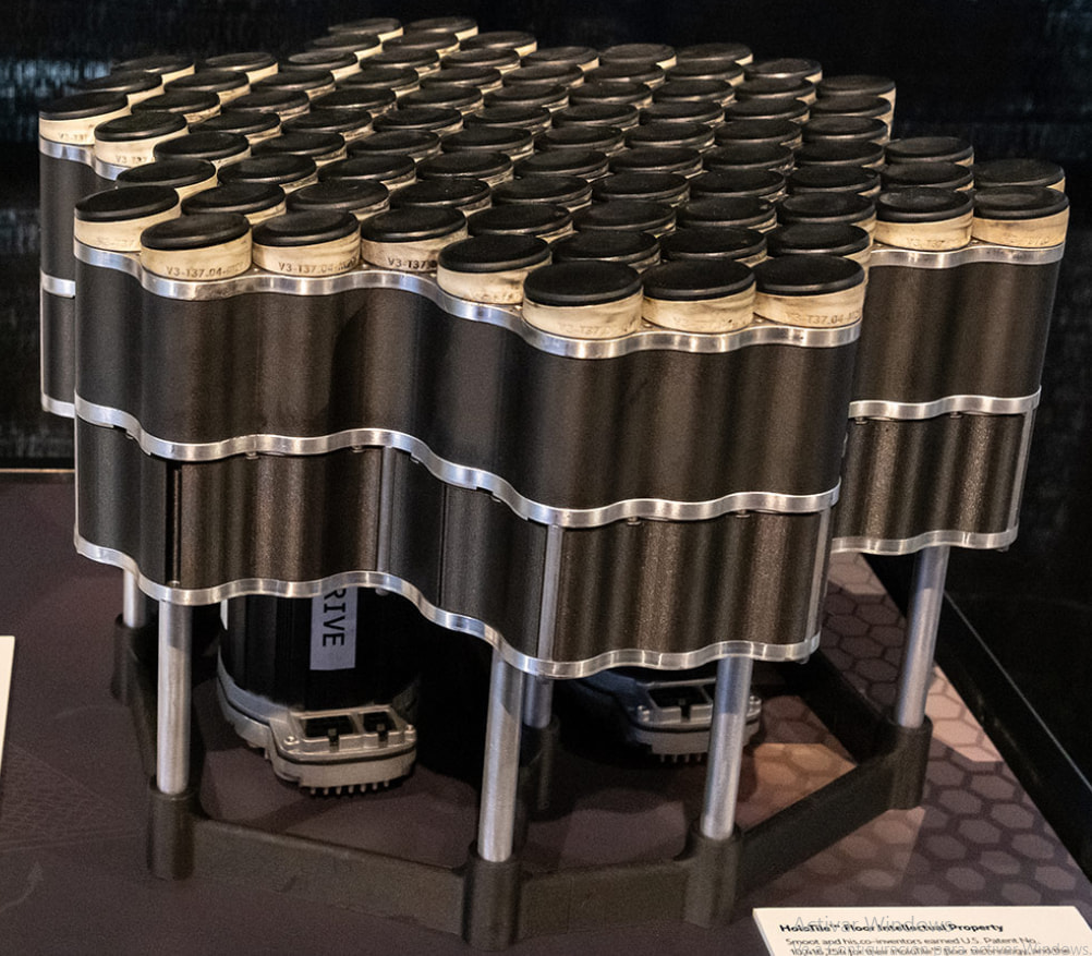
The design should be thin: the DIY HoloTile should be as thin as possible. If it was very tall it wouldn’t be practical for a normal room. For reference, here is Disney’s HoloTile design, which takes up to 30cm from the floor to the HoloTile surface: Go to => IMAGE1
-
No need for multi-user/object control: the DIY HoloTile only needs to keep the VR user in the middle of the surface.
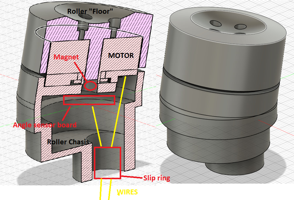
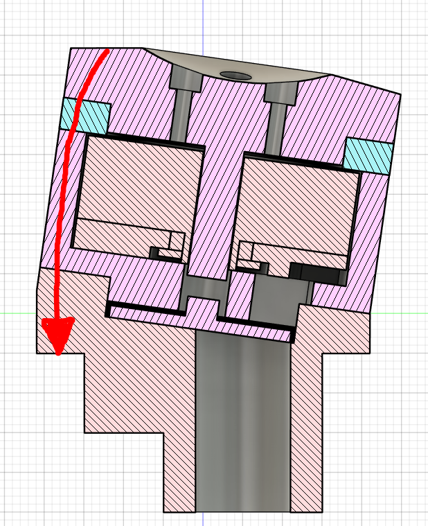
With these objectives in mind, I started designing how a DIY HoloTile could be. My current design uses small low KV gimbal BLDC motors on each rotary surface to move the user. To point the rotary surface in the correct direction, the support of the motor will have an excentric to rotate it. This allows the design to be very thin and also not use gears which are noisy. Potentially the design could be thinner than 10cm from the floor to the DIY HoloTile surface. To detect the position of the shoes, I had the idea of using a thin film pressure sensor on each rotary surface. Here is the design of a single rotary surface module: Go to => IMAGE2
And here is how the DIY HoloTile would work: Go to => VIDEO1
To drive these small motors I wanted to use an easy-to-get cheap driver because it is very this part of the design is very cost sensitive. I think the SimpleFOC Mini board is the right selection for this. As for the angle sensor, I wanted to use a magnetic one to help with low-speed performance. I also wanted to use SPI for communication because that is recommended. The best economical option I found is the MT6816 sensor boards.
To control the drivers, magnetic angle sensors and pressure sensors, I was recommended the STM32G474VET6 developer boards. Apparently, it is able to generate the signals for 7 drivers (in 3PWM mode) and read the angle sensors (with the help of DMA) and pressure sensor (with the help of DMA). Another nice thing about this board is that it is CANFD capable, so it could be connected to a master board to send pressure sensor data and receive motor speed commands. Here is possible pinout configuration: Go to => IMAGE3
This is the first time I have worked with STM32 and before committing I wanted feedback about the design in general and especially about the control set up. What things would you change in the design? What components would you replace? What are the next steps for developing SMT32?

Hey, the link isn't working anymore. I'm really curious to see the video, could you please re-send it? Thanks!
– The1TrueWill