Gimble BLDC motor: Very very poor performance compared to standard ESC

Hello,

I’m trying SimpleFOC to replace a classic 6-step BLDC commutation driver for a gimble motor. This motor works very robustly using traditional 6-step commutation tecnique with BEMF. I’ve used it both with a my own prototype controller and with commercial ESC.

In SimpleFOC, The motor “works”. ie It spins, and it works quite well as a servo-positioning system in angle mode, but in velocity mode, speed and torque are nowhere even close to what I get using traditional ESC. I cannot get it to spin faster than ~1K RPM in openloop, or over ~600RPM -in closedloop (I get ~3K with my ESC)… I didn’t measure torque, but with simpleFOC it’s not even close to traditional BLDC with ESC.

Are my expectations right? I thought I read that FOC control would always match or beat traditional commutation?

Controller Arduino Uno (ATMega328P@16Mhz)
Driver: FOCShield v234,
Motor: small 12v 90KV gimbling motor 17 ohm phase resistance,
Sensor: AS5600 in I2c mode

(it isn’t FOCStudio which is holding this back, performance is same without studio)

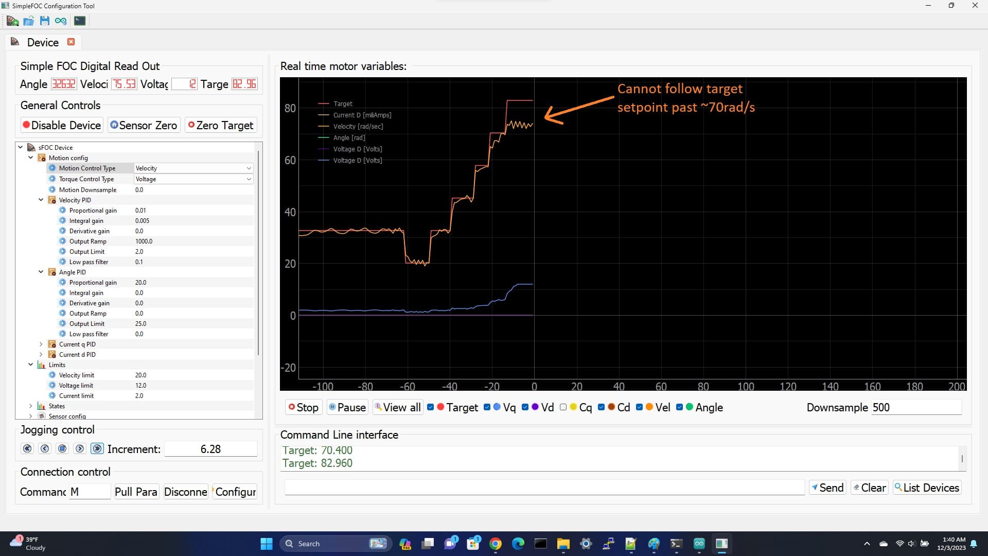
(attempt to get velocity target past 70 rad/s)

Code:
#include <SimpleFOC.h>

BLDCMotor motor = BLDCMotor(7, 17);
BLDCDriver3PWM driver = BLDCDriver3PWM(9, 5, 6, 8);
MagneticSensorI2C sensor = MagneticSensorI2C(AS5600_I2C);
//InlineCurrentSense current_sense = InlineCurrentSense(0.01f, 50.0f, A0, A2);

// include commander interface
Commander command = Commander(Serial);
void doMotor(char* cmd) { command.motor(&motor, cmd); }
void doTarget(char* cmd) {command.scalar(&motor.target, cmd);}
void doLimit(char* cmd) {command.scalar(&motor.voltage_limit, cmd);}

void setup(){
driver.voltage_power_supply = 12;

Serial.begin(115200);
motor.useMonitoring(Serial);
motor.monitor_variables = _MON_TARGET | _MON_VOLT_Q | _MON_VOLT_D | _MON_CURR_Q | _MON_CURR_D | _MON_VEL | _MON_ANGLE; // monitor target velocity and angle

// link driver
driver.init();
motor.linkDriver(&driver);

// link the motor to the sensor
sensor.init();
motor.linkSensor(&sensor);
motor.voltage_sensor_align = 2;
// contoller configuration based on the controll type
motor.PID_velocity.P = 0.01;
motor.PID_velocity.I = 0.01;
motor.PID_velocity.D = 0;
// velocity low pass filtering time constant
motor.LPF_velocity.Tf = 0.1f;
// angle loop controller
motor.P_angle.P = 10;
// angle loop velocity limit
motor.velocity_limit = 25;

// initialise motor
motor.init();
// align encoder and start FOC
motor.initFOC();

// add the motor to the commander interface
// The letter (here ‘M’) you will provide to the SimpleFOCStudio
command.add(‘M’,doMotor,‘motor’);
command.add(‘T’, doTarget, “target”); // ssss space
command.add(‘L’, doLimit, “voltage limit”);
// tell the motor to use the monitoring
motor.monitor_downsample = 0; // disable monitor at first - optional

}
void loop(){
//…
// iterative function setting the outter loop target
motor.loopFOC();
motor.move();
//…
// real-time monitoring calls
motor.monitor();
// real-time commander calls
command.run();
}

What microcontroller are you using?
The I2C may be one reason. Do you have any encoder with AB or SPI outputs?

Sorry I’m using Arduino Uno (ATMega328P) (I’ll update the OP).

I’ve tried in the past to use the AS5600 in analog mode without success (I’ll try this again).

I don’t know the FOC algorithm in any depth yet, but is position feedback required to maximize torque and RPM?

I also wonder if current feedback is the reason?. My Driver has this capability but My Uno doesn’t have the Flash memory to compile it in :frowning: Is that important for RPM/Torque?

The PWM mode is maybe even worse than the I2C mode, because it is even slower (PWM period is few kHz whereas I2C clock is ~400kHz). The position feedback is crucial to the algorithm working efficiently.

The ATMega328P (8-bit, 16MHz) is quite slow, is it possible to move to a more modern platform (32bit, clock speeds > 100MHz)? Combined with the I2C sensor, your loop frequency is probably quite low.

It has a PWM mode, but it also has a true alalog output mode, where it outputs 0-5V proportional to the position (I’ve used this mode in other projects). It also has a PWM mode but I’m not considering that.

1 Like

If you have these square white AS5600 boardds, you have to unsolder a resistor to make it work in analog mode. It works much faster than I2C, but it’s noisy.

I don’t remember which resistor it was, but I found this tip in the net.

1 Like

Yes, I’ve done the resistor mod and am using the board in analog mode(I have done this before). The noise is actually very small, around 1LSB with the motor off.
Unfortunately though this didn’t solve the problem and I’m still getting absolutely pitiful performance.

Is this even supposed to work with an ATMega328@16hz??? I mean, I bought the shield board thinking the arduino would have the horsepower to run FOC. Does anyone use an arduino UNO with this???

I could try another platform but im just pouring tremendous amount of time getting this $$&@@$ thing to work already :frowning: and switching to another platform like Esp32 would be another time sink maybe for nothing

I think most (or at least many?) people are using this with the STM32 Nucleo boards which have the same form factor. I think the Uno is not really a recommended platform for a while now.

You certainly will notice a difference in performance between ATMega328p and any STM32, ESP32

If all you need is 6 step, there is a good controller, here, that does this, Amazon.ca . These are a common type, there are many variations and I have found they work well except they are to noisy for me.

They are the only kind that I have found that can reliably drive gimbal motors. And I’ve tried like 13 different ones.

If you want roll your own driver, the b-g431-esc1 board works ok, there is certainly much room for improvement but you can hobble with it.

But you should realize that designing a motor driver de novo is not trivial, even with the help of SimpleFOC as a building block. It is only a building block, it’s not a suite of plug and play components. Hopefully we will get there some day, for now imo the next step is to make a good board which is an improvement on the b-g431-esc1 board. That’s one plug and play component. Soon after, a few more will follow.

yeah I found that, too. Most of the boards are stuck in programming mode, basically, because of a resistor that’s in the wrong place. That’s why they don’t output analog.

Analog isn’t perfect either though, one issue I discovered is that of course the signal can’t change instantly so you get a glitch where it drops suddenly, this looks like the motor has suddenly reversed direction for a short period. I filtered it out, but it’s annoying.

There is a better magnetic sensor, that uses spi which is a lot faster than i2c, the sdc6002 or something. I forget exactly. I got some boards made with it and people have reported good results and it’s cheap and has good specs and available through jlcpcb. I have like 10 spares if you want them, built into some breakout boards.

I already have a mature 6-step commutation sensorless product that I target to ATMega32x platform (hence my choice of that platform)

The reason I’m here is I’m trying to explore benefits of FOC (vs. 6-step commutation). From what I’ve read FOC should provide better performance in almost all key metrics (velocity, torque, efficiency) but I’m just not seeing this. It looks like maybe the ATMega32x just doesn’t have the cycles to run this algo, something I wish I’d know before jumping into this.

Yes, your right, I’ve been a bit lazy on deep-diving into the FOC algorithm and was maybe foolishly hoping this library would wrap or abstract this complexity but if I’ve learned anything in 30 years of engineering there’s no substitute for deep understanding of the algorithm your trying to use.

Hi @sgordon777,

Once correctly tuned and set up, you would expect FOC control to have better torque than the six-step, especially at slow speeds / from rest.

The fact that the 6-step ESC outperforms the FOC running on an ATMega328 with I2C based sensor doesn’t surprise me. FOC is far more computationally intensive.

So I think the problem here is twofold:

  1. The I2C sensor is too slow - it will introduce a large delay to your FOC loop which will limit the number of iterations you can achieve per second. This will have a direct impact on the maximum speed you can achieve.

  2. The UNO itself is too slow. Running FOC even with a faster sensor you won’t get much more than a few kHz iteration speed. This will limit your performance in terms of the max speed.

So switching to a faster MCU and faster sensor will greatly increase your loop speeds, and open the door to higher motor speeds.

Whether you can then make the motor turn faster depends on the tuning, the drive voltage and of course the load on the motor.

Yeah, FOC is more of an end state. You have to get the whole system working properly to achieve real FOC, that is optimal magnetic field vs. rotor angle at all times.

If you think about it, clearly this end state is superior to 6 step commutation in the respects you described. Nothing could be better than having that angle close enough to optimal at all times. But that’s not going to happen unless all the timing is pretty good, there is very low sensor error etc.

I found out the hard way there are a lot of sources of error here. I looked briefly and I didn’t see any sensor calibration, for instance. You gotta calibrate these magnetic angle sensors, and even then the error from the sensor alone for various reasons can be enough to make the energy efficiency on the low side, worse than 6 step for sure.

I’ve experimented a lot with a fan by driving the motor in various ways, and nothing I ever tried was more than very slightly better than the 6 step driver I indicated. Not even manual tuning. If you simply send the motor a certain voltage and frequency (for a fan), and then adjust the voltage downwards, you get a dip. The motor timing, this relationship between magnetic field angle produced by the coils/stator and rotor angle, will be optimal at some point, because it increases when you reduce the voltage. Then the current will actually go up if you continue decreasing the voltage. I’ve never been quite clear on that part, I don’t know why it doesn’t stall exactly at the optimal point.

But by simply running the motor open loop and adjusting the voltage very carefully I can see exactly what steady state optimal drive looks like within like 1% error margin. In terms of what it sounds like, energy efficiency I get etc.

It’s way better than any of the other drivers except that six step one I referred to, get. It’s even better than a dedicated FOC chip from Texas instruments made for fans and another one from Allegro could get, even when I tuned them all according to their instructions etc.

What this says to me is that a) Sensorless drive has more potential than people think. It’s not a cheapie option. Because the sensor is the motor, you could nearly eliminate sensor error, although there might be other ways to do this as well.
b)most commercial options aren’t nearly as good as people think. They were designed by people like us and management did not let them do what they needed to do to do a good job.

p.s. I don’t know why the 6 step one does as well as it does, I can only suppose that the optimal drive waveform is not a sine wave, for the motor.

I’ve dod the same. Basically an AS5600 with I2C is just too slow as is the Arduino. This is why six-step commutatin is used so much – because it is easy and does not need $30 worth of electrincs to drive a small motor.

The reason you would use FOC is for better perfomance and for that you have to pay the price for a top-end sensor and a 32-bit mirocontroller. I’ve had good luck with ESP32 and RP2040.

Not oly is the 5600 slow, it is noisy. Yu cam improve the noise by reducug the air gap between the magnet and chip. I was actualy able to get a gimble motor to run with your same setup but it was not ideal.