It looks like I will eventually need to make custom driver boards. I will need about two dozen of them. I think it will have
DRV8305
some microcontroller
FETs for low average current but high peaks up to 30+ amps, more if I can.
some kind of buss interface, maybe CAN bus.
likely low-side current sense because it is easier to design. Or maybe inline hall-effect sensors? I will have to prototype a few ideas…
I can likely handle the design as I can copy known to work ideas. I have some solderless breadboard stuff going together now. I’m using ESP32 and RP2040 to see which I like and I have 3 or 4 Nucleo boards handy, May have to move to STM32. I can get a bead board working.
My question is how to build it. I have done some PCBs using JLCPCB. They are great if they have the parts. They don’t have parts to build this, certainly not the DV8305 and only limited STM32 parts, but no RP2040 or ESP32.
In fact, no one seems to have the ability to build this.
Is it reasonable to have JLCPCB build a board and solder on the passive parts, then I add some chips like the microcontroller and DRV8305 myself at home with a low-cost reflow oven?
I’m a total novice with reflow. I have some questions
how fine of a lead pitch is reasonable for a novice like me to attempt, with near 100% good results. I think maybe the DRV83o5 is possible, but I doubt the RP2040 is. I can hand solder an ESP32 module.
Can you reflow one more chip to an already made board? As said I think I might have JLCPCB solder all those 0805 sized passive parts then I reflow a few more chips they don’t have.
Or is there a cost effective way to have the entire thing built offshore in China?
I do need to consider manufacturing this early in the process As I don’t want to design an unmanufactureable solution
That depends, if you rely on a stencil, for applying paste, then already reflowed parts is going to interfere with the process. You may need to reflow both sides with different pastes @different temperatures. The first side with high temp, second side, while first side is downwards, with lower temp then melting point of first side.
My reflow oven is controlled by a UNO switching a typical 230v Solid State Relay. no biggi. It just has to be the correct type of heating element that heat up fast.
I would likely never build an oven. For PCBs under 100 mm square, I’d use one of these. T962 Reflow Oven
Yes, I’ve read the reviews and the suggested upgrades are cheap, easy enough to do.
I think using a stencil would be nearly impossible if there were already parts on the board. So what is the limit on footprint feature size working with no stencil, assuming non-superhuman skills.
The other thing is I have no control over the kind of solder paste JLCPCB uses. Andthey can chnge paste type at any time.
The other thing is that they only put components on one side. I don’t know yet if this is good or bad. It means that one side will always be clear
It’s neither good or bad, but it is limiting for sure.
Some components, I believe, stick to the underside by way of liquid retention or stickiness of the paste. You know, like the way some insects skate on water, just opposite.
It would be quite impossible. For the stencil to work, it has to be tight against the board, and held tightly in a frame. The frame stretches the stencil and when you release it lifts it in a way that doesn’t smear the paste. None of this is possible if the board has anything on it.
For a board with parts already on it you can apply solder paste from a syringe…
Some people do this stuff all the time… so yes!
In theory you can reflow a board with parts on it. But you have to use a lower temperature solder paste, otherwise the existing parts will all come loose. Surface tension may hold them in place, but it may also pop them out of place. Better not to risk it.
The critical thing is to try it out first on some test objects. Practice is everything. I think after playing around for a few hours with some tests you’ll have a feeling for your current limits.
There are dedicated “solder practice kits”, also for SMD, that you can buy as test objects
I answered that one actually only from the point of view of feasibility. From the point of view of cost, none of this is “reasonable”.
Yes, JLC is a bit more limiting in what you can do to achieve their excellent prices, but services like PCBWay (which I use a lot) or others are far more flexible. You can send PCBWay some Gerbers (electronically) and a bunch of parts (by mail) and they will make a board and assemble it for you, sourcing any missing parts themselves.
It costs a little more than JLC, but its also more bespoke.
But this is “cost effective” only if you’re in the business of developing a product, or you’re being paid to prototype, or similar situation.
For a “maker” or hobbyist, the reason to make your own PCB is for the fun of it, for the learning experience, or to build something really new or unique.
For a motor controller, it is almost always far more cost effective to buy a finished unit from ODrive, Texas Instruments, or whatever, even if it costs $300… by the time you’ve paid for PCBs, components, assembly and shipping, a reflow oven, solder paste and other equipment, wasted some boards and account for all your time - well, then you can probably buy many $300 ODrives for that money.
Nonetheless, I fully understand anyone who wants to roll their own I’m on my 6th produced design, with many more that didn’t make it to production. And @Valentine seems to design several of them per week in fact, maybe we should put a warning on the site that this is addictive
Yes, JLC have both RP2040 and ESP32 in stock. I just checked, right now.
Could you please clarify who is “no one”? You mean yourself or JLC?
May be yes, however, this is very difficult since some of the parts are already soldered and you will break their temperature profiles and may destroy the existing parts. Some parts cannot be re-heated like cold pizza in the oven. Also the mechanics are extremely hard because you cannot use a solder mask anymore and have to manually deposit the solder paste.
I’m a little confused, isn’t that what JLC does? You design your board and send the design the JLC, they fabricate it and mail it to you?
For a motor controller, it is almost always far more cost effective to buy a finished unit from ODrive, Texas Instruments, or whatever, even if it costs $300
I need two dozen of these. $7,200 is not going to work.
I did not say why I’m doing this. so here it is…
The goal of this project is to create a quadruped robot like the MIT Cheetah for under =< $80 per joint. The MIT lab built a great robot but they did not care about cost and used full CNC metal parts and very expensive motors. I want to show that you can build one for under $1,000. I have one now, scratch built for about $300 but I used hobby R/C servos and it is “sluggish” to say the least. I use it as a software development platform.
Said another way. The goal is to see how much performance I can buy for $1,000, I will reduce the specs to fit the budget.
Using JLCPCB is one way to maximize performance for a fixed hard budget. If I can get the controller even $1 lower price, that means I can put $1 more into the motor.
This is a fixed sum game.
So the budget is $80 for
A BLDC motor, I can find a suitable one for about $30 and a better one for $60. I might be able to use a mix.
a 9:1 gear reduction system. I think 3D printed plastic can work. I only need 100 hours before rebuilds but my tests are going well. Using a sun and planet system. The plastic costs $2 and a set of ball bearings costs maybe $12
a driver board. If I can do this for $30 I’m good. I think I can if I can use JLCPCB, if I can design to what they can do.
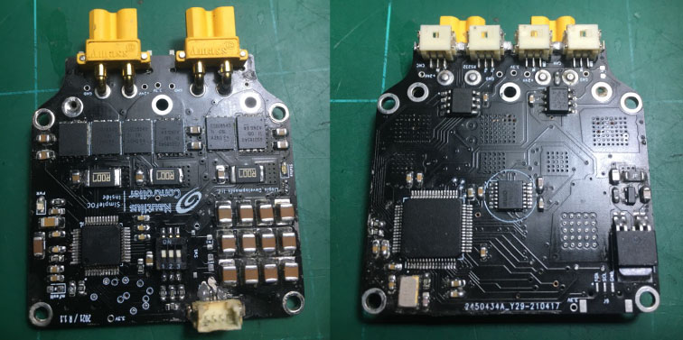
This is a fully integrated (MCU, drivers and mosfets and comms), SimpleFOC driver board for a 60mm to 70mm motor, with the performance characteristics you described, fully manufactured by JLC, for a batch of 10 board they will manufacture it for $110, but shipping is extra (about $20) to the States, so total 130 for 10 boards with shipping, that’s $13 for one board. You may be able to get a $10 discount per order and get ground shipping for $4 (110-10+4) so you could get this for about $10.40 per board.
This is a fully integrated (MCU, drivers and mosfets and comms), SimpleFOC driver board for a 60mm to 70mm motor… …so you could get this for about $10.40 per board.
I have been playing with some designs and thought I could get close to that price. But I was not confident enough to say I could. I only have hand drawn schematics and, handwritten BOMs, and it was looking like well under $20.
I would might want different packaging, but electrically the same thing. I’ve not figured out if the drivers should mount to the motors or be inside the body. I’ve have to look at both ways in CAD.
Mounting to the motors has the advantage of fewer wires, especially if you use ESP32’s wireless for communication. Plus you can usually get away with finer gauge because the motor wire current is usually much higher than the battery wire current.
And if the electrical distance between each driver is very small, they should be able to share capacitors to some extent. That’s one reason my version of the Lepton is designed to be stacked along a single pair of 2mm wires, so there’s only a few mm between each board. With a separate pair of power wires going back to the battery for each board, the capacitors are effectively isolated from eachother by the long electrical length.
Another advantage to central location is that a single fan can cool all of them. Though if you’re going with passive cooling, then mounting to motors is better to avoid concentrating all the heat in one place.
One bit of advice I give to others, that I should take is “You are not building your last widget, you are building your first widget.”
There will likely be 2nd and third revisions.
People who believe they are deigning the last device try and do every possible optimization and add every feature. But really, the goal should be to be conservative and reduce risk.
JLCPCB’s current price for the DRV8305 chip is $235 per chip. This is not going to be built until the market returns to normal.
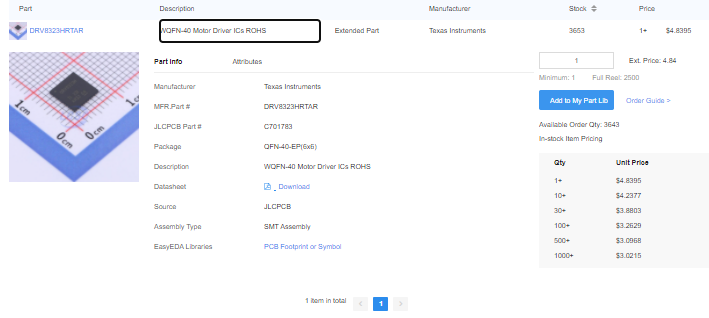
The market is back to normal. There are so many other drivers out there. Why are you so attached to this particular driver? The much better driver DRV8323 for example is only $4 and in stock. Don’t you think there may be a really good reason why DRV8305 is not in stock and so very expensive? Like, it’s old and not used anymore and only legacy designs are using it and that’s why the supply is so low and high price reflects the demand?
Thanks for pointing out the DRV8323. If nothing else they have greatly improved the data sheet. There is lots of good information there.
I’m not attached to any one chip. I was using the 8305 as a reference for cost estimates. I’ll used the 8323 now. Next up is hunting JCPCB;s site for deal on mosfets. I whish they had better seach tools
What I just might do is make a “bench tool”, have JLCPCB make the reference circuit from the data sheet with no microcontroller. With a design that is “breadboard friendly” This way I can try different uP chips I have. and a few encoders
What I’d like is to push as much of the real-time motion control as I can down to the motor controller.
My goal is to have one leg on a test stand this year.
Could you please elaborate on this? When you say “have JLCPCB make the reference circuit from the data sheet”, you mean you will ask them to design the PCB for you based on a circuit from the driver documentation sheet?
I did the assembly manually with a soldering iron, a hot air gun and a microscope. I did not use any stencil, It was the first time I made a “non trivial” board … it worked well.
The mosfet search works reasonably well in my experience. Diver search, not so much. I have no idea how Valentine found that DRV8323, but it looks excellent The datasheet does indeed have a lot more useful and comprehensible information than other driver datasheets I’ve tried to read.
For mosfets, try selecting a current range like 80-250A, and voltage 40-100V, and then select some of the lower RDS(on) values that are available. That should get you mostly 5x6mm size. It would be nice if you could search by package, but there are a million different variants of the 5x6 size and they’re all mixed in with other sizes in the list.
This is my favorite one I found: HSBA4086 HUASHUO | Transistors/Thyristors - LCSC Electronics Relatively low voltage limit of 40V, but a mere 0.8mOhm resistance. With my heavy conductor tricks, that should allow some very high power with minimal heating. And you can’t go very much higher voltage anyway without losing the ability to use 50V 10uF 1206 capacitors.
I will use KiCAD to produce design files that implement the reference design in the data sheet. This reference design has no microcontroller, so the design is simple. Then have JLCPCB make the boards.
I’ve not decided on a microcontroller. I have RP2040, ESP32 and some Nucleos here.
I’m working on another PCB design right now, not related Simple FOC. I’ll wait until I have a few projects ready to take advantage of combined shipping.
BTW, I’m using MicroPython for the first time on that other project. I’m very impressed. It is much faster and better I thought it would be.