Curious, what causes gate Ringing across the gate of a mosfet?
Running the half bridge without load, I received a very nice square wave. My on and off voltages are as expected… I believe the gate to be well saturated.
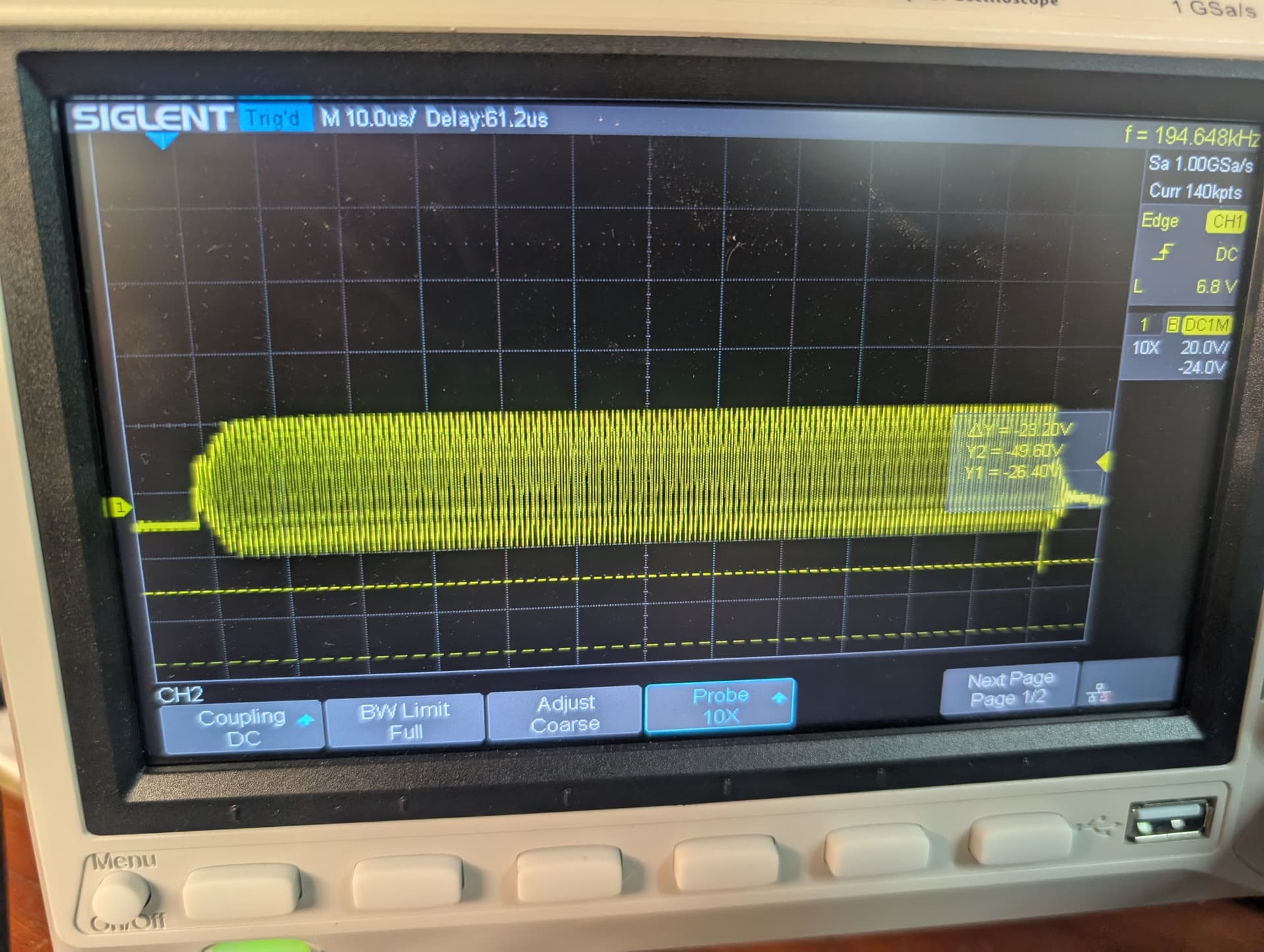
Adding a 60v supply and then applying a 50 ohm load I received some ringing. Is this normal ?
I am running my pwm at 1000 hz.
Output from the mosfet driver:
Power supply is 15v and -5v for the driver.
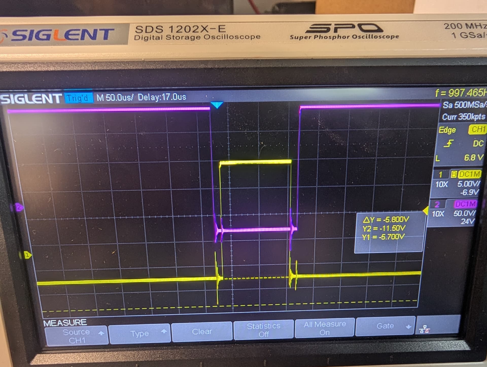
Output of mosfet driver across gate after 60v is applied
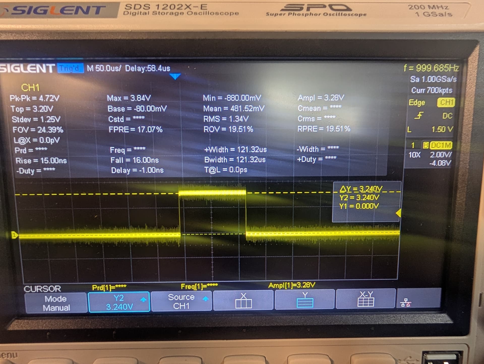
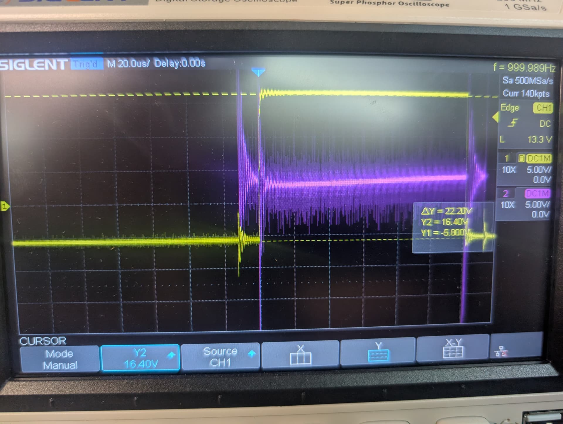
Plc waveform:
This is the pwm signal coming from an STM uC. 3.3v signal
I’ve had a look at the oscilloscope screenshots provided and they don’t make much sense. I suggest you label which voltage each trace is measuring, and also provide the circuit diagram for others to have an easier time interpreting the data.
In your first screenshot, the magnitudes of the waveforms seem off, likely because you have configured your probes incorrectly. In the first screenshot, the purple trace jumps from around 150V to -50V, and the yellow trace jumps from -6V to 17V.
In your second screenshot, it seems like the gate voltage has some very high frequency oscillations which seem to be undamped, gate ringing oscillations always show up as a damped waveform. Also, the voltage of this waveform goes from -16V to 24V, which isn’t a typical gate driving voltage.
In your third screenshot, critical information (time per division, voltage per division, zero voltage marker) has been cut off so it isn’t possible to interpret the meaning of the waveform given.
If you are able to give me some better data, I can help you debug your circuit.
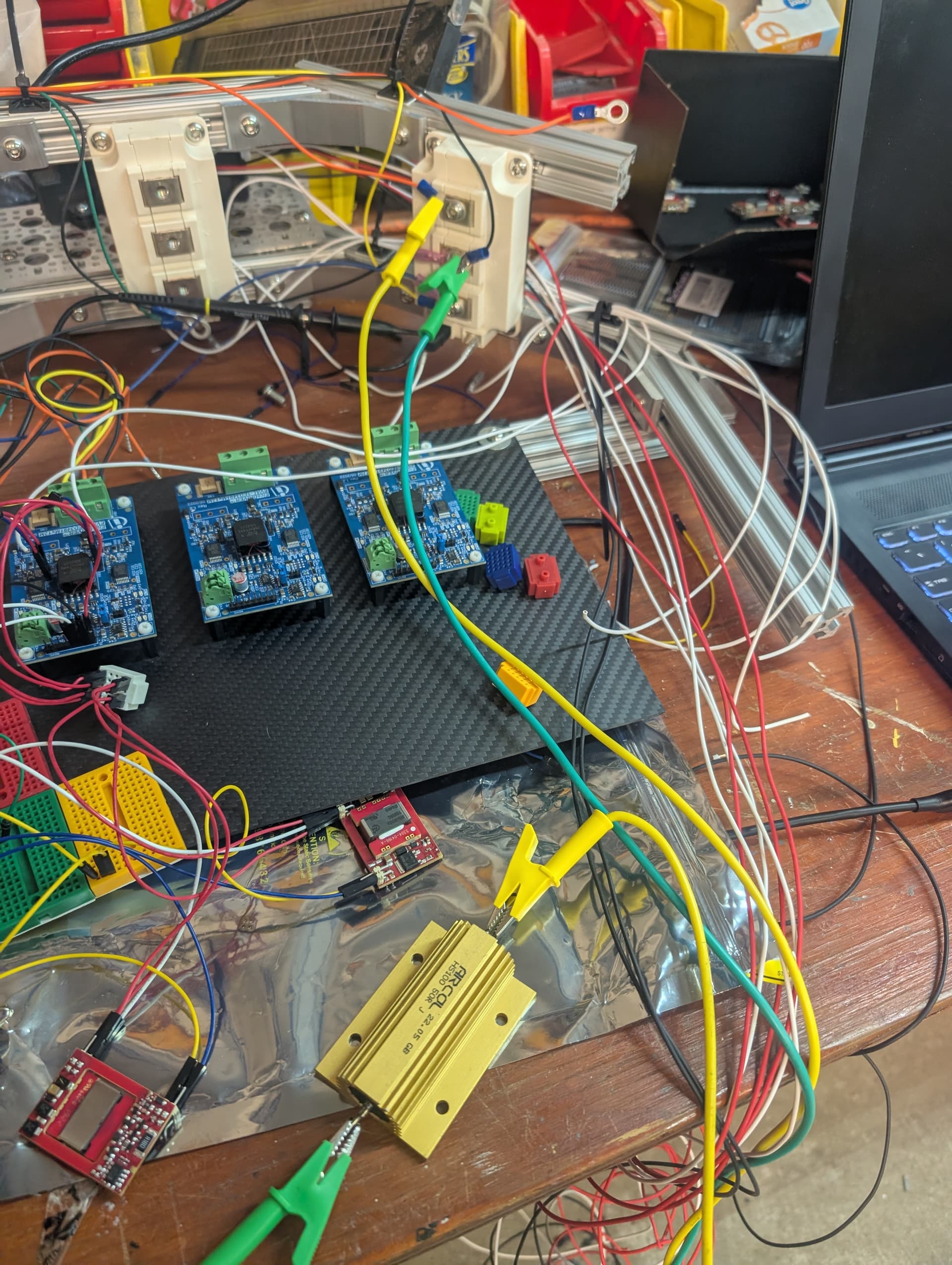
Also very important to show your measurement setup for things like these - a little too much (loop) inductance in your probing technique and you’ll pick up all kinds of things
I was hoping to avoid sharing the unkept nest of wires…
Maybe my first trouble shooting step will be to clean up the breadboarding a bit.
Thank you for the feedback.
I am going to take a step back and clean up some of the wiring.
I did repost photo 3 with the rest of the scope screen visible.
I also retook photo 3… But am not getting even more noise.
Again… I am going to take a step back and clean up the test setup.
From your picture, I can see that you have wired up a high voltage gate driver eval board, but there are no MOSFETs soldered in there. Maybe this is why it isn’t working?
The white chunky blocks on the aluminium extrusions are the mosfets right? I’m fairly certain the parasitic inductance of the wires running to the gates are causing the ringing. You want these as twisted and as damn short as possible!
1 Like