Hey, check out these mice sensors! They have a 12.000fps resolution 50g acceleration and 16.000 cpi
400ips
It has a SPI interface
Hey, check out these mice sensors! They have a 12.000fps resolution 50g acceleration and 16.000 cpi
400ips
It has a SPI interface
Could u make a rotary encoder with this. The x and y movements of the wheel should somehow be translated to angle / rotation. If you ha a wheel with say 3 inches circumference. You suddenly have a 16000 x 3 resolution over 360 degrees. 48.000 counts per rev. This should obviously be narrowed down a bit
Edid: If the wheel is wide, one can measure the distance traveled. The sensor can be zerroed at any given time.
400 ips is ca. 10 meters / sek
What is this angle snapping class ?
Edid_ Angle snapping is a smoothing function. It removes jitter at high speed/fps
")
How do you do DMA - SPI interface; direct memory access
You could, but you are essentially wasting an axis. Just look down at the wheel surface. A more interesting use for wheeled robots is to look at the ground to detect actual vehicle motion, rather than infer it from wheel odometry. This detects effective steering, motion from casters, weight or ground shifts, being pushed, wind, etc.
Coupled with ordinary resolution wheel odometry, you have a wheel slip detector.
What if you measure the face of the gear. Could you not calculate a angle and or velocity from sensed x and y coordinates x time.
Are you saying the downlooking cam should do the encoding ? (pnp robot)

Yes. Downlooking cam does the encoding. If you mount just 1 in the front or rear bumper(not axle) with cam(X,Y) alligned with vehicle(X,Y) you can capture real vehicle speed and direction with optical flow. With careful one time measurements of your wheel positions relative to the sensor, you can use reverse kinematics to determine what wheel movements would be required to produce the observed motion. Compare that against the actual commanded wheel movements to judge the accuracy of your model. Once you are sure your model is good, discrepancies are wheel slip.
Alternatively, if what you want is just wheel rotation encoding, don’t bother measuring anything. You need one sensor per wheel. Point the sensor looking down at the top of the wheel, with only the tread surface in view. Optical flow will be in the opposite direction of wheel rotation. The radius on top is not necessarily the same as the rolling radius for soft tires. I said it was wasting an axis because the same thing could be done with a single axis line array sensor. Though having 2 axis makes mounting accuracy much less critical.
With some ingenuity one can attach a aluminium, carefully cut to size, heatsink with threaded holes
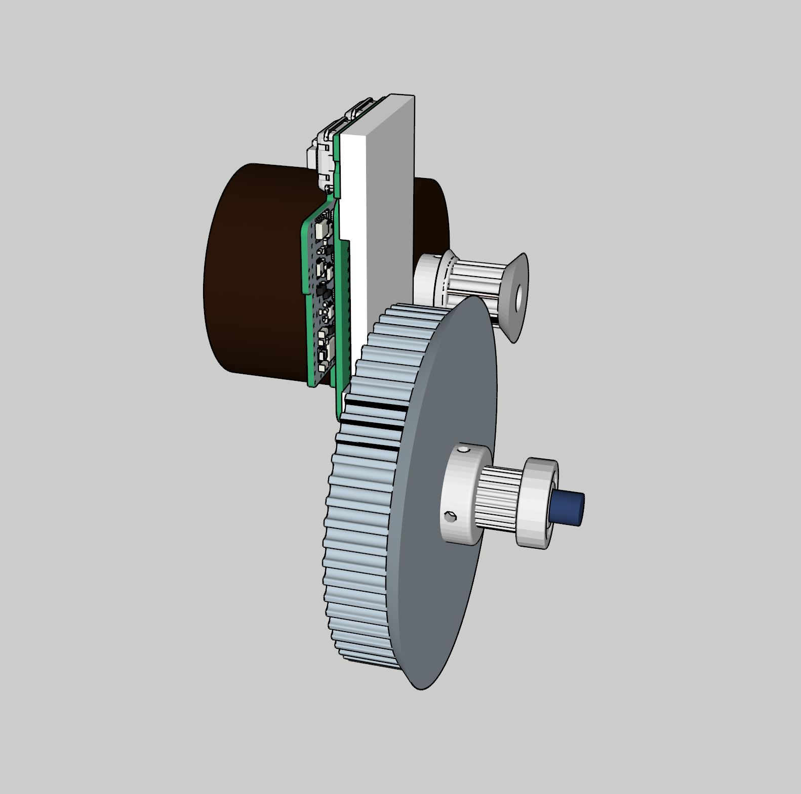
Sensor center is approx. 17mm from shaft center.
This is how I see the gear face against the optical sensor. For it to work it would need integration with the in motor hall encoders. The downlooking cam does the homing of the machine. In that process the optical sensor is also homed or zeroed. In this image i’ve used 12 teeth pulley on the motor, 58 teeth on the gear and 25 teeth on the GT2 9mm belt pulley. The gear and GT2 pulley chare a shaft rotating in 8mm bore skate bearings.
So, when the motor spins 5 times, the machine moves x (pulley teeth count) x 2mm for GT2
With a 5mm shaft the teeth count on the GT2 belt can become lower.
If the sensor is 30mm from the center the circumference will be around 7 inches. The sensor can be set to eg. 3000 counts per inch. That’s 21.000 counts per rotation on the gear and per 50mm movement. 21000/50mm = 420 counts per mm. Movement 0,002380952380952 (The sensor can go up to 16.000 counts per inch but will probably have less error margin at lower settings)
In other words, when the motor spins one rotation the machine moves 10mm
Here is a 12 tooth GT2 pulley. This will give a 24mm rotation and 4.8mm movement per motor rotation.
I can’t make out what the optical sensor is looking at. Gear teeth? The side of a gear? You do not want its depth of focus to change greatly, nor be centered on an object rotating in its field of view. If it is looking at the flat side of the gear, near the edge, but not at the teeth, you should be fine. Rough up the surface to reduce reflections and cast tiny shadow details for it to track. Everything in its field of view should be moving with uniform motion, like the view a mouse sees.
I don’t know if this will work as a commutation sensor, it might. I’m really interested to find out. I was talking about using it as a position sensor.
I was reading https://community.simplefoc.com/t/different-encoders-for-commutation-and-position-loop/410
at the same time and mentally merged the 2 threads with my own robot control problem. Hope I wasn’t confusing.
Obviously the window shall be over the face. But counting teeth would also be a way. Here ive sketched a 3D printeble gear with 300 x 1mm holes around the belt retainer. That´s 600 states if using a single optical sensor / light sensor. if one rotation is 36mm (18 teeth GT2 pulley) then 600 states is (36mm/600 states=0,06mm precision.
Or use it as the brim, for good bed adhesión. To avoid warping

Hijo te amo por siempre [posterity}