That looks awesome @David_Gonzalez. Mesmerising. Have you thought about putting a pen on the end and doing some weird drawings like a harmonograph or cycloidal drawing machine?
I’m looking to use SimpleFOC with an esp32. Any tips? I’m, perhaps naively, trying to use this polyfil for esp32 that provides an analogWrite implementation (it uses ledcWrite under the hood):
Thank you @Owen_Williams! I have though about that I’m just not sure what would be the best way to go about that? Maybe I should implement G-code interpretation. Do you have any suggestions?
I can say that the ledc will not work properly. You will have to use MCPWM, but it’s a bit difficult to get it working properly. Paul Gould (Three Phase Centre Aligned MC PWM | Details | Hackaday.io) found a mistake in the MCPWM’s arduino implementation that is necessary to to obtain center aligned PWM signals. Shoot me a message through Hackaday and I will help you setup the library to run on the ESP32.
There doesn’t seem to be any way to synchronize PWM signals with ledc. You need to have center aligned PWM signals for the motor to see “true” sinusoidal signals. @Antun_Skuric explained to me why this is important a few months ago and the stability difference between center aligned and not center aligned PWM signals in my robots is enormous.
I’m (trying) to use the polyfill above at the moment. It works ok for openloop but I reserve judgement on it for closed loop until I do further testing. I’m fairly new to motor theory. I think what your saying is that ledc is left aligned?, whereas MCPWM can do center alignment. My intuition is that left aligned won’t be a problem if the analogWriteFrequency was say 100x greater than the frequency that we wish to update the pwm duty/value. If the two frequencies are similar then it may always be HIGH as the change in duty will cause the pwm to reset HIGH and we’ll skip the part where duty is LOW. I can see how center frequency would likely be better but it could have the opposite problem i.e. too frequent duty changes could yield the first LOW part of duty cycle being ‘replayed’ too much. LOW is probably safer though.
ledc functions are left aligned and MCPWM are center aligned what makes a big difference.
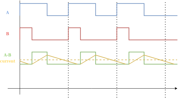
One of the most important reasons is the difference of the current waveform the two singals produce.
Here is an image of center aligned pwm signal
This is just a simple example.
In general the reason we are setting the voltage to the motor is because we want to generate torque, which is proportional to the current of the motor. This basically means that we would like to control the current. Current has its own dynamics, and it cannot follow the fast changes of the PWM signal but it more or less filters the mean value. You can see that on both images in yellow.
Now, when you have center aligned PWM signal the signal the resulting PWM signal the motor sees (A-B) in green will be balanced in time and divided in two, which will maintain the minimal variance of the current. When you have the left-aligned PWM you will have a lot loger HIGH times and LOW times making the current waveform much more oscillatory, what makes the motor torque more oscillatory.
Due to these long stationary values, it is even possible that the current drops to zero at some point, what would mean that there would be no generated torque on the motor for some time.
As @Owen_Williams said if the PWM frequency is high enough these effects are less visible. But in general, current dynamics are under 1ms so you would need to go above 50kHz or even more in order to filter this behavior, what is in many cases impractical.
Therefore in reality especially for lower duty cycles the difference can be substantial.
The other reason why center aligned PWM is used, is because of the architecture of the bldc drivers.
In our case we are controlling the set of upper mosfets (PWM 1,3,5) and lower set (PWM 2,4,6) is generated in BLDC drivers directly, essentially they invert the PWM signal sent to the upper ones. They perform much more efficient when you change only one signal at the time. Only one set of mosfets at the time. For the case of left-aligned pwm, you will be always changing all three sets of mosfets at the beginning of the PWM cycle.