First project, fallen at first hurdle!

I am really keen to use FOC to give me good motor control and have a few projects lined up to use this.
Unfortunately I’ve had a couple of false starts with this sytem but have returned to my first project and I’m really hoping to make a go of it this time.

This first project was, I thought, relatively simple in that I simply want to spin the motor at an RPM, ideally between around 50-2000RPM and update periodically based on input from a speed sensor of some description - For now just a single hard-coded value.
I have been working with a friendly AI bot to help me along but it seems to be getting out of its depth and throwing anything at it without much rhyme or reason.

Ultimately the project will define the speed value via processing another input such as ADC, I2C, SPI or GPS but for now, to keep things simple, I’m using a hard-coded value.
Also for simplicity I want to drive the motor initially in open loop mode, hence not currently using an encoder although I have one available (tested and working).

I initially deployed a sketch and wired up the motor (IFlight IPower Motor GM3506 130T) and drive board (SimpleFOC Mini v1.0) as AI suggested, uploaded the program to the ESP and nothing happened!

It seems logical to me to take a step backwards, take the drive board and motor out of the equation and check if I’m even getting the derired output from the ESP, my take on this is that if I don’t get to that point anything downstream is irrelevant?
My expectation is that, if the program is doing its job, I should get a PWM output on each output?
The PWM will have var

I have done this today via 'scoping the output connections and I don’t see any activity on them.
I did also issue some code to place a simple PWM output on these pins and this did work indicating that the pins are PWM capable.

Indications on this page:

seem to indicate that my ESP32-S3 can use any pins for MCPWM (Motor Control PWM?) and that timer and pin association is performed automatically by SimpleFOC.

It seems that even simpler boards (S2, C3) can alternatively use LEDC for PWM but presumably it is not required for me to look further into this as my board should be good with MCPWM.
I have tried using pins 4, 5 & 6 and 35, 36 & 37 each time with no success.

I am programming via the Arduino IDE and have linked to the latest SimpleFOC library and ESP board manager so hopefully have the best available?

My take on this at the moment is:
My expectation of the ESP producing the PWM output is wrong.
There is a problem with the code.
There is a problem with my ESP (I do have an alternative available, ESP-WROOM-32)

I’ve reproduced the text of the sketch below. I’m new to this so may have missed some detail, please don’t hesitate to ask. As always thanks in advance for any help.
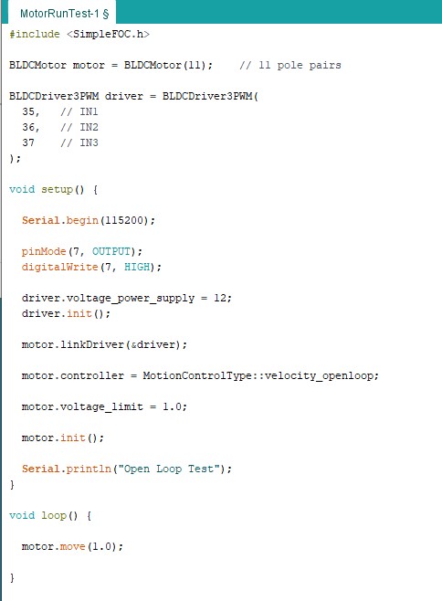
I think that the issue is the loopFOC.
Add motor.loopFOC(); to the loop in addition to the motor.move();.

This is needed from v2.4.0

Thanks for your very prompt reply @Antun_Skuric I’ll give that a go first thing and let you know how it goes.

I wonder, how many example files come with the 2.4 library, which aren’t working anymore because of this line missing…

Yeah, there aren’t that many actually. I’ve updated all the docs. The only ones that I forgot are the open loop examples in the library. But yeah, many people start with them and hit the wall right away… Sorry about that!

@Antun_Skuric I have added this command and the motor is now working, thanks for your help with this.

The motor runs quite smoothly at low RPM, better than expected, particularly considering this is currently open loop, presumably could be better once encoder is added.

I’ve added some code in the loop to increase the RPM but I’ve found that I hit a limit once I go from 150 to 300 RPM.
This does increase if I increase :
motor.voltage_limit = x.x;

This started at 1, now increased to 3 and I the RPM before stalling has also increased but only to about 600RPM.
I guess I could hike the “motor.voltage_limit” further but I’m a bit worried about any negative consequences, presumably there must be a limit anyhow.
Would this be likely to improve with a closed loop system?

Nice!
Ok I’d suggest you to use the estimated_current torque control mode where you can set the desired current limit (not the voltage limit).

You only really need the KV rating and the phase resistance of your motor for it. That should not be too difficult to find.

Using this control mode the library will automatically calculate the appropriate voltage to compensate for the Back-EMF voltage and you’ll not need to update the voltage limit by hand.

See more info here:

And with respect to the efficiency of different open-loop methods, see this:

Thanks @Antun_Skuric, I’ll look into that.

I did try a higher voltage but found that the motor started to get hot as the RPM went up. This is with no load on the motor which would indicate not very efficient working so something is not ideal. But it’s early days yet and I need to get into a bit more detail. I’m just happy at the moment to have the motor spinning.

Are you aware that the motorspeed is in rad/s not RPM? 300rad ~ 3000RPM which is not bad for a gimbal motor.
The openloop examples are there to test your wiring and pin-definitions, it doesn’t make much sense to waste time on tuning/maxing. The risk to burn up the driver isn’t worth it.

Hi @o_lampe , thanks for the input. I am up to speed on the units and I have put a calculation into the code so I can code in RPM while driving in Rad/Sec, I just kept that out of my code sample to save any confusion.

In terms of the advice against open loop, I absolutely agree with this, it was always the intention to use closed loop and the motor that I have has an encoder built onto it. However, working alongside this project is my learning process so I thought I’d push a bit further to see what is possible with open loop and what the downsides are. Working this way has also raised a few aspects for my brain to chew on so I’m glad I’ve spent some time with it. Today’s project though is to build it up into an open loop system.