Hi @runger bit of an update, I have got almost everything working. I can’t get the PWM function working.
void* pwm1params;
pwm1params = _configure1PWM(1000, A_PWM);
_writeDutyCycle1PWM(50, pwm1params);
The analog write is working, so currently using that.
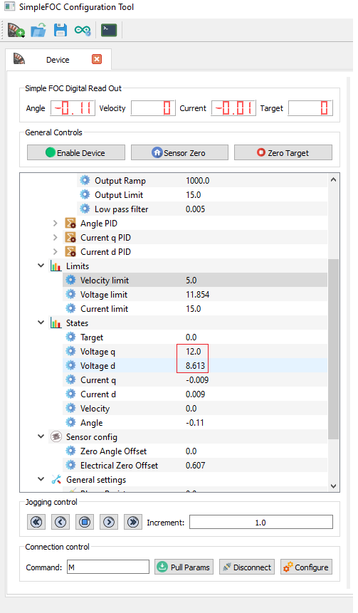
The other problem I have is when ever I disable the motor under load or in motion the PIDs keep calculating and give motor full voltage/current when I enable the motor again. Is there away to set all these to 0 and stop calculations while motor is disabled?
Here is the motor protection code for the B_G431B_ESC1 so far with braking and works well if anyone else is interested, it’s messy and unfinished, just add to your libs folder.
Header
#ifndef motorProtection
#define motorProtection

#include "Arduino.h"
#include <SimpleFOC.h>


class mpClass{

  public:
    //Declare all Functions
    void begin();
    void loop();
    void reset();
    float readVbus();
    float readTemp();
    void doMotorProtectCommand(char *command);
    float mpPID(float SP, float PV, float P, float I, float D, float Min, float Max, float Cycle);

    void linkMotor(BLDCMotor*);
    void linkEncoder(Encoder*);
    void linkBLDCDriver6PWM(BLDCDriver6PWM*);
    void linkLowsideCurrentSense(LowsideCurrentSense*);

    float brake_P = 1;
    float brake_I = 10;
    float brake_D = 0;
    float brake_Min = 0;
    float brake_Max = 250;
    float brake_Cycle = 0;
    unsigned long update = 1000;

    float brakeEngageOffset = 0.25;
    float brakeEngageMaxOffset = 2.0;
    float brakeEngageMaxDisableOffset = 3.0;
    float brakeCutOffPeriod = 250;

    float temperature;
    float tempCutOff = 60.0;
    float tempDelayPeriod = 500;

    float stallDelayPeriod = 100;
    float stallCurrentOffset = 0.1;
    float stallVoltageOffset = 0.1;

    float overCurrentOffset = 0.05;
    float overVoltageOffset = 0.05;
    float overCVDelayPeriod = 100;

    int mVelCnt = 6;
    float mVelOffset = 1;
    float mVelPeriod = 250;

    int mAngleCnt = 8;
    float mAngleOffset = 0.1;
    float mAnglePeriod = 500;

    int mCurrentQcnt = 10;
    float mCurrentQoffset = 1.5;
    float mCurrentQperiod = 100;

    int mCurrentDcnt = 10;
    float mCurrentDoffset = 1.5;
    float mCurrentDperiod = 100;

    int mVoltageQcnt = 10;
    float mVoltageQoffset = 1.5;
    float mVoltageQperiod = 200;

    int mVoltageDcnt = 10;
    float mVoltageDoffset = 1.5;
    float mVoltageDperiod = 200;

    class internal{
      public:
        bool oscillating(float input, int cnt, float offset, float period);
        float input;
        int cnt;
        float offset;
        float period;
      private:
        bool out;
        bool outNew;
        bool init;
        float oldValue;
        int cntUp;
        int cntDown;
        bool dirUp;
        bool dirDown;
        bool osOscillating;
    };

  private:

    float VBus;
    float pwmPID;
    float pwmDuty;

    bool motorVoscillation;
    bool motorAoscillation;
    bool currentQoscillation;
    bool currentDoscillation;
    bool voltageQoscillation;
    bool voltageDoscillation;

    byte brakeMode;
    #define brakeOff 1
    #define brakeEngage 2
    #define brakeEngageMax 3
    #define brakeEngageMaxDisableMotor 4

    BLDCMotor* motor;
    Encoder* encoder;
    BLDCDriver6PWM* driver;
    LowsideCurrentSense* currentSense;


};
#endif
#include "motorProtection.h"

//Motor Protections will disable motor
//Will self reset fault condition if in safe condition and allow you to enable motor again
//Motor Protection functions Include:
//Bus Overvoltage Braking
//Temperature Protection
//Stall Protection
//Over Current / Voltage Protection
//Oscillation Protection

//Link all objects from main ( not all are needed but here for future )
void mpClass::linkMotor(BLDCMotor *motorReference){
  motor = motorReference;
}
void mpClass::linkEncoder(Encoder *encoderReference){
  encoder = encoderReference;
}
void mpClass::linkBLDCDriver6PWM(BLDCDriver6PWM *driverReference){
  driver = driverReference;
}
void mpClass::linkLowsideCurrentSense(LowsideCurrentSense *currentSenseReference){
  currentSense = currentSenseReference;
}

//Create instance for function call per object
mpClass::internal VClass;
mpClass::internal AClass;
mpClass::internal CQClass;
mpClass::internal CDClass;
mpClass::internal VQClass;
mpClass::internal VDClass;

void mpClass::doMotorProtectCommand(char *mpCommand){
  switch (mpCommand[0]){
  case 'R':
    reset();
  break;
  case 'D':
    motor->disable();
  break;
  case 'E':
    motor->enable();
  break;
  case 'V':
    Serial.printf("Bus Voltage Reading: %f \n", readVbus());
  break;
  case 'T':
    Serial.printf("G431 Temperature: %f \n", readTemp());
  break;
  }
}

void mpClass::reset(){
  //Reset/Restart Driver reinitialize driver and motor calibration
  //TODO
}

bool mpClass::internal::oscillating(float input, int cnt, float offset, float period){
  if (!init){
    oldValue = fabs(input);
    init = true;
  }
  if (fabs(input) > (oldValue + offset)){
    dirUp = true;
    dirDown = false;
  }
  else if (fabs(input) < (oldValue - offset)){
    dirUp = false;
    dirDown = true;
  }
  else {
    dirUp = false;
    dirDown = false;
  }
  oldValue = fabs(input);

  if (dirUp)cntUp++;
  else if (dirDown)cntDown++;

  if (cntUp >= cnt && cntDown >= cnt){
    if(!osOscillating){
      out = true;
      osOscillating = true;
    }
    else{
      out = false;
    }
  }
  else{
    out = false;
  }
  static long delayOscillating = millis();
  if (millis() - delayOscillating > period) {
    cntUp = 0;
    cntDown = 0;
    out = false;
    osOscillating = false;
    delayOscillating = millis();
  }
  return out;
}

//Important call from class and assign object for static variables!
//Must always be called in loop!
float mpClass::mpPID(float SP, float PV, float pGain, float iGain, float dGain, float Min, float Max, float Cycle){
  static unsigned long previousMicros;
  static float pErr;
  static float Err;
  static float P;
  static float I;
  static float D;
  static float Out;
  if (micros() - previousMicros >= Cycle) {
    previousMicros = micros();
    Err   = (SP - PV);
    P     = (pGain * Err);
    I     = (I+(Err*iGain*Cycle));
    if(I > Max) I = Max; //Prevent Integral windup
    else if(I < Min) I = Min;
    D     = (dGain*(pErr-Err)/Cycle);
    pErr  = Err;
    Out   = (P + I + D);
    if(Out < Min) Out = Min; //Clamp output to the limits
    else if(Out > Max) Out = Max;
  }
  return Out;
}

float mpClass::readVbus(){
  float vbus = _readADCVoltageLowSide(A_VBUS, currentSense->params);
  vbus = vbus * 10.7711;
  return vbus;
}

float mpClass::readTemp(){
  float tADC = _readADCVoltageLowSide(A_TEMPERATURE, currentSense->params);
  static const float ResistorBalance = 4700.0;
  static const float Beta  = 3425.0F;
  static const float RoomTempI = 1.0F/298.15F; //[K]
  static const float Rt = ResistorBalance * ((3.3F / tADC)-1);
  static const float R25 = 10000.0F;
  float temp = 1.0F/((log(Rt/R25)/Beta)+RoomTempI);
	temp = temp - 273.15;
  return temp;
}

void mpClass::begin() {
  driver->voltage_power_supply = readVbus();
  motor->voltage_limit = driver->voltage_power_supply;
}

void mpClass::loop(){
  static unsigned long previousMicros;
  if (micros() - previousMicros >= update) {
    previousMicros = micros();
    //Read Bus voltage
    VBus = readVbus();
    //Call PID
    pwmPID = mpPID(driver->voltage_power_supply, VBus, brake_P, brake_I, brake_D, brake_Min, brake_Max, brake_Cycle);
    //Disable Motor If bus voltage to high, otherwise let's dump it through brake resistor
    static bool osBrake;
    if (VBus > (driver->voltage_power_supply + brakeEngageMaxDisableOffset) && (motor->shaft_velocity > 0.01)) {
      static long delay = millis();
      if (millis() - delay > brakeCutOffPeriod && !osBrake) {
        brakeMode = brakeEngageMaxDisableMotor;
        SIMPLEFOC_DEBUG("Bus Voltage to high, Disable Motor: ", VBus);
        delay = millis();
        osBrake = true;
      }
    }
    else if (VBus > (driver->voltage_power_supply + brakeEngageMaxOffset) && (motor->shaft_velocity > 0.01)) {
      brakeMode = brakeEngageMax;
    }
    else if (VBus > (driver->voltage_power_supply + brakeEngageOffset) && (motor->shaft_velocity > 0.01)) {
      brakeMode = brakeEngage;
    }
    else if (VBus < (driver->voltage_power_supply + 0.1)) {
      brakeMode = brakeOff;
      osBrake = false;
    }

    switch(brakeMode)
    {
      case brakeOff:
        pwmDuty = 0;
      break;

      case brakeEngage:
        pwmDuty = pwmPID;
      break;

      case brakeEngageMax:
        pwmDuty = 245;
      break;

      case brakeEngageMaxDisableMotor:
        pwmDuty = 250;
        motor->disable();
      break;
    }

    analogWrite(A_PWM, pwmDuty);
    //TODO get the _writeDutyCycle1PWM working
    //Should not be using analogWrite
    //void* pwm1params;
    //pwm1params = _configure1PWM(1000, A_PWM);
    //_writeDutyCycle1PWM(0.5, pwm1params);

    static bool osTemp;
    temperature = readTemp();
    if (temperature > tempCutOff){
      static long delay = millis();
      if (millis() - delay > tempDelayPeriod && !osTemp) {
        motor->disable();
        SIMPLEFOC_DEBUG("Driver Over Temperature, Disable Motor: ", temperature);
        delay = millis();
        osTemp = true;
      }
    }
    else{
      osTemp = false;
    }

    //Detect if motor has stalled and shutoff controller
    static bool osStall;
    if (fabs(motor->current.q) >= (motor->current_limit - stallCurrentOffset)) {
      if (fabs(motor->shaft_velocity) < 0.01){
        static long delay = millis();
        if (millis() - delay > stallDelayPeriod && !osStall) {
          SIMPLEFOC_DEBUG("Motor Stalled Current, Disable Motor: ", motor->current.q);
          motor->disable();
          delay = millis();
          osStall = true;
        }
      }
    }
    else if (fabs(motor->voltage.q) >= (motor->voltage_limit - stallVoltageOffset)) {
      if (fabs(motor->shaft_velocity) < 0.01){
        static long delay = millis();
        if (millis() - delay > stallDelayPeriod && !osStall) {
          SIMPLEFOC_DEBUG("Motor Stalled Voltage, Disable Motor: ", motor->voltage.q);
          motor->disable();
          delay = millis();
          osStall = true;
        }
      }
    }
    else{
      osStall = false;
    }

    //Over Current and Over Voltage Protection
    static bool osOverCV;
    if ((fabs(motor->current.q) >= (motor->current_limit + overCurrentOffset))){
      static long delay = millis();
      if (millis() - delay > overCVDelayPeriod && !osOverCV) {
        SIMPLEFOC_DEBUG("Motor Over Current, Disable Motor: ", motor->current.q);
        motor->disable();
        delay = millis();
        osOverCV = true;
      }
    }
    else if (fabs(motor->voltage.q) >= (motor->voltage_limit + overVoltageOffset)){
      static long delay = millis();
      if (millis() - delay > overCVDelayPeriod && !osOverCV) {
        SIMPLEFOC_DEBUG("Motor Over Voltage, Disable Motor: ", motor->voltage.q);
        motor->disable();
        delay = millis();
        osOverCV = true;
      }
    }
    else{
      osOverCV = false;
    }

    //Detect if Motor is in an uncontrollable state ie oscillating
    motorVoscillation = VClass.oscillating(VClass.input = motor->shaft_velocity, VClass.cnt = mVelCnt, VClass.offset = mVelOffset, VClass.period = mVelPeriod);
    motorAoscillation = AClass.oscillating(AClass.input = motor->shaft_angle, AClass.cnt = mAngleCnt, AClass.offset = mAngleOffset, AClass.period = mAnglePeriod);
    currentQoscillation = CQClass.oscillating(CQClass.input = motor->current.q, CQClass.cnt = mCurrentQcnt, CQClass.offset = mCurrentQoffset, CQClass.period = mCurrentQperiod);
    currentDoscillation = CDClass.oscillating(CDClass.input = motor->current.d, CDClass.cnt = mCurrentDcnt, CDClass.offset = mCurrentDoffset, CDClass.period = mCurrentDperiod);
    voltageQoscillation = VQClass.oscillating(VQClass.input = motor->voltage.q, VQClass.cnt = mVoltageQcnt, VQClass.offset = mVoltageQoffset, VQClass.period = mVoltageQperiod);
    voltageDoscillation = VDClass.oscillating(VDClass.input = motor->voltage.d, VDClass.cnt = mVoltageDcnt, VDClass.offset = mVoltageDoffset, VDClass.period = mVoltageDperiod);
    if (motorVoscillation   ||
        motorAoscillation   ||
        currentQoscillation ||
        currentDoscillation ||
        voltageQoscillation ||
        voltageDoscillation){
      SIMPLEFOC_DEBUG("Motor Oscillating, Disable Motor");
      motor->disable();
    }
    if (motorVoscillation) SIMPLEFOC_DEBUG("Motor Shaft Velocity Oscillating");
    else if (motorAoscillation) SIMPLEFOC_DEBUG("Motor Shaft Angle Oscillating", motorAoscillation);
    else if (currentQoscillation) SIMPLEFOC_DEBUG("Motor current Q Oscillating");
    else if (currentDoscillation) SIMPLEFOC_DEBUG("Motor current D Oscillating");
    else if (voltageQoscillation) SIMPLEFOC_DEBUG("Motor voltage Q Oscillating");
    else if (voltageDoscillation) SIMPLEFOC_DEBUG("Motor voltage D Oscillating");
  }
}
How to use: Add these your main file
//Motor Protection Instance
mpClass mProtection;
void doProtection(char *cmd){
mProtection.doMotorProtectCommand(cmd);
}
//ADD to your Setup/Begin
pinMode(A_PWM, OUTPUT);
//Enable SimpleFOC Debugging
SimpleFOCDebug::enable(&Serial);
// use monitoring with serial
Serial.begin(115200);
//Call at end of your setup!
//Motor Protection Settings
//Link all objects for motor protection class
mProtection.linkMotor(&motor);
mProtection.linkEncoder(&encoder);
mProtection.linkBLDCDriver6PWM(&driver);
mProtection.linkLowsideCurrentSense(¤tSense);
//Protection update rate in microseconds
mProtection.update = 250;
//Brake PID Paremeters
mProtection.brake_P = 10;
mProtection.brake_I = 100;
mProtection.brake_D = 0;
mProtection.brake_Min = 0;
mProtection.brake_Max = 250;
mProtection.brake_Cycle = 0;
//Brake Trigger (driver power supply + Offset amount above vbus)
mProtection.brakeEngageOffset = 0.25;
mProtection.brakeEngageOffset = 2.0;
mProtection.brakeEngageMaxDisableOffset = 3.0;
mProtection.brakeCutOffPeriod = 200;
//Temperature Settings
mProtection.tempCutOff = 60.0;
mProtection.tempDelayPeriod = 500;
//Stall Detection
mProtection.stallDelayPeriod = 100;
mProtection.stallCurrentOffset = 0.1;
mProtection.stallVoltageOffset = 0.1;
//Over Current/Voltage Protection
mProtection.overCurrentOffset = 0.05;
mProtection.overVoltageOffset = 0.05;
mProtection.overCVDelayPeriod = 100;
//Oscillating Detection
//Shaft Velocity
mProtection.mVelCnt = 6;
mProtection.mVelOffset = 1;
mProtection.mVelPeriod = 250;
//Shaft Angle
mProtection.mAngleCnt = 8;
mProtection.mAngleOffset = 0.1;
mProtection.mAnglePeriod = 250;
//Current Q
mProtection.mCurrentQcnt = 10;
mProtection.mCurrentQoffset = 1.5;
mProtection.mCurrentQperiod = 250;
//Current D
mProtection.mCurrentDcnt = 10;
mProtection.mCurrentDoffset = 1.5;
mProtection.mCurrentDperiod = 250;
//Voltage Q
mProtection.mVoltageQcnt = 10;
mProtection.mVoltageQoffset = 1.5;
mProtection.mVoltageQperiod = 250;
//Voltage D
mProtection.mVoltageDcnt = 10;
mProtection.mVoltageDoffset = 1.5;
mProtection.mVoltageDperiod = 250;
//Add Cammand for Motor Protection
command.add('P', doProtection, (char*)"Motor Protection");
//Call Motor Protection Setup
_delay(500);
mProtection.begin();
//Run this in the loop after motor.move
//Call Motor Protection Loop
mProtection.loop();
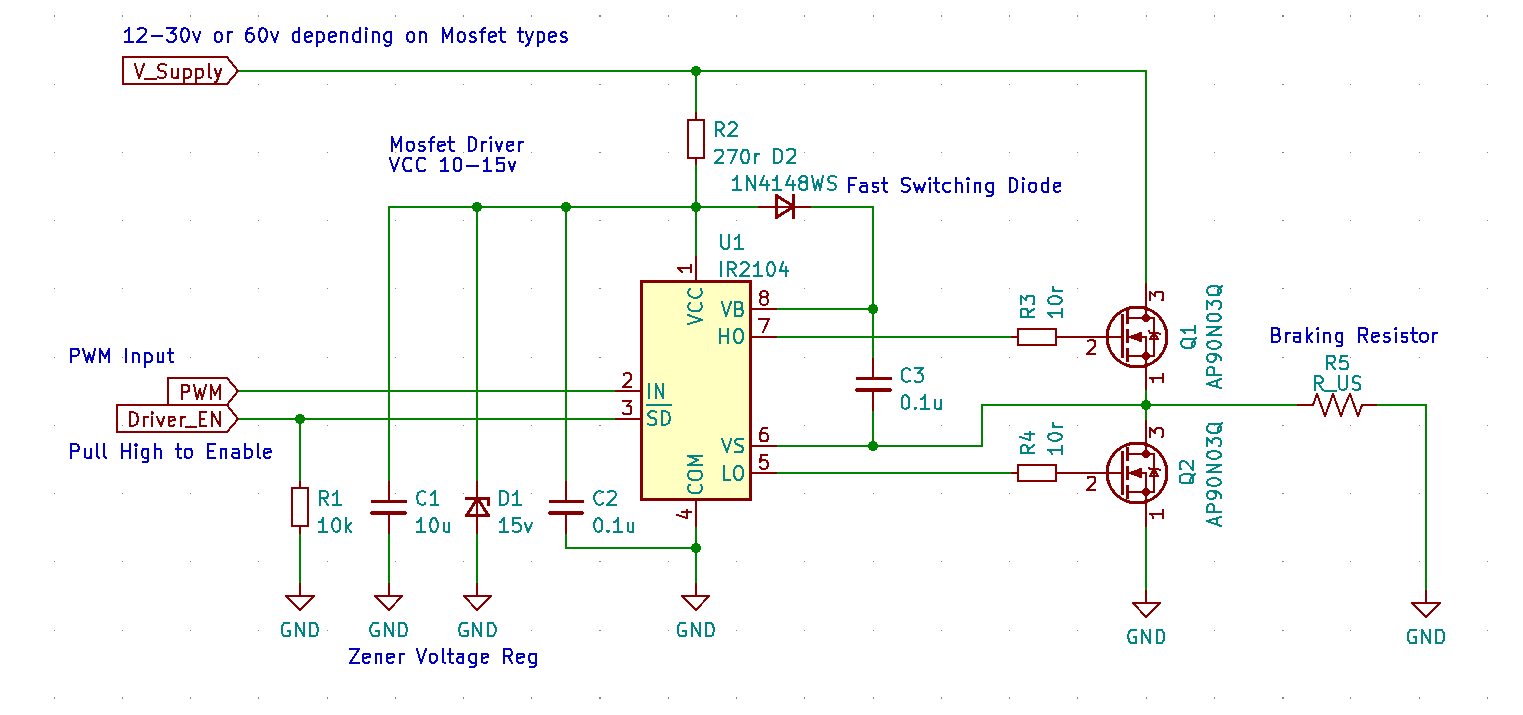
Here is the braking circuit I am using with the B_G431B_ESC1
Hopefully it helps others and is a good start, I will add to my github when I have everything working correctly