The voltage divider is like a sensor on a analog input.
Here I have made it with a 0805 resistor. You kan calculate the current going through it and try to hit 3 volt, when VIN is 35V. If you use a 20K resistor, there is going to flow 1.75 milliamp through the resistor @ 35 volt
I think I urgently need to follow this advice to understand what’s going on here ![]()
Yes, trip the bridge when the voltage on the analog pin goes beyond a certain value. As far as I understand, a voltage divider, there is not going to flow current into the analog pin.
The purpose of the brake resistor is to keep the bus voltage below the PSU over-voltage protection trip point. By knowing the bus voltage, through the voltage divider, we know when to start letting current through the brake resistor.
I found room for a thermistor on the main VIN, to monitor the bus temperature. It to is a kind of voltage divider.

How long is a typical large spike on the voltage?
Can we catch it inside the main loop, with a digital comparison? Analog read or is is better to use the IC analog comparator? In the case of the Analog comparator, I think there are some pins tro rule out.
I took a look at your spread sheet ![]() what is the precision calculations based on? Any change you could give a simple explanation somewhere inside the doc.
what is the precision calculations based on? Any change you could give a simple explanation somewhere inside the doc.
Just found this informative thread on Odrive. From what i gather, the IC calculates the voltage on the bus based on the current flowing through the shunt´s. Does SimpleFoc do this?
This might be a trivial question, but at the moment my head is in hardware mode.
Has anyone looked into this some more? I have been running simpleFOC on an Odrive copy board I made quite some time ago and have the brake mosfets installed and want to run it off a power supply rather than batteries. I damaged my old power supply running motors with large inertia and fast deacceleration. What would be required to add this functionality?
1 Like
I’m slowly working on it… had to do a bunch of other things first, like adding an API to control the phases into Hi-Z mode. That work is now done, so I could get to work on the next parts…
I’ve now also got 2 new test-setups with slightly higher power motors on my desk and am trying to figure out the best way to attach weights to them to give them more inertia.
Code will go here for the moment: Arduino-FOC-drivers/src/motor at braking · simplefoc/Arduino-FOC-drivers · GitHub
But what’s there right now isn’t tested or working, and still needs to be developed into something real ![]()
1 Like
Hi @runger that’s good to hear there has been a start. When do you think you will get back into it? Have you built some hardware with braking resistor?
Hi @Matt303 ,
I think I have only 1 or 2 drivers that include any kind of braking circuits, I have to check… I’ve never used them since SimpleFOC hasn’t supported it, so I’m unsure.
I’ve made a test setup for experimenting with braking and coasting, and I was going to look into coasting and braking modes that don’t need an external resistor first, since people can run these on most drivers.
Braking with external circuits was further down the list in terms of my plans, because it needs special hardware. It probably also needs additional voltage and current sensing channels, which is another task I have to work on in the software before I can test it, because currently we don’t support using the ADC for tasks other than current sensing of the motor phases.
I assume eventually I will have to make my own board or spend some $$ on an ODrive or ODrive clone. I’ve already started on a design ![]() with an eye to that future need.
with an eye to that future need.
I’m sorry I can’t spend more time on this (really - I’d love to!) but I have to fit it in with work, family and other interests… and there are constantly other tasks and bug fixes to look at also. So if its left to me, it might still take a while ![]()
1 Like
Hi @runger yeah that’s understandable. Have you got more details about your custom board?
I was thinking, could we not just monitor the bus voltage and we have PID to regulate the H-Bridge the brake resistor is connected to when the voltage rises above set level? The PID will maintain the bus voltage? As long as this setpoint is higher than the input voltage it will just dump any voltage spikes on the bus?
Sound reasonable to me. The bus should obviously have capacitors to catch/dampen any large spikes. The problem with spikes when braking, as far as I’m aware, is many large consecutive spikes raising cap/voltage like a boost circuit ?
Hi @runger
Does this mean I can not use simple analogRead and analogWrite in the main loop?
After some digging around through the code. I see the functions used.
  float VBus = _readADCVoltageInline(A_VBUS, currentSense.params);
  VBus = VBus * 10.7711;

  void* pwm1params;
  pwm1params = _configure1PWM(10000, A_PWM);
  _writeDutyCycle1PWM(50, pwm1params);
Would this be correct?
yeah, that should definately be avoided. On some MCU types it may work, but on others not so much.
You seem 100% on the right track here - with this kind of code you can init a 1-PWM output to control a braking FET, and read an analog voltage.
The problem with the analog part is that this won’t work at the moment I don’t think - at least not in combination with other current sensing. I think only on RP2040 would we support reading an additional ADC channel along with the 2 or 3 phase channels, but the API for doing so isn’t properly exposed either.
This is unfortunately work in progress on our side, but if you don’t mind “hacking” I’m sure you could get something working for yourself…
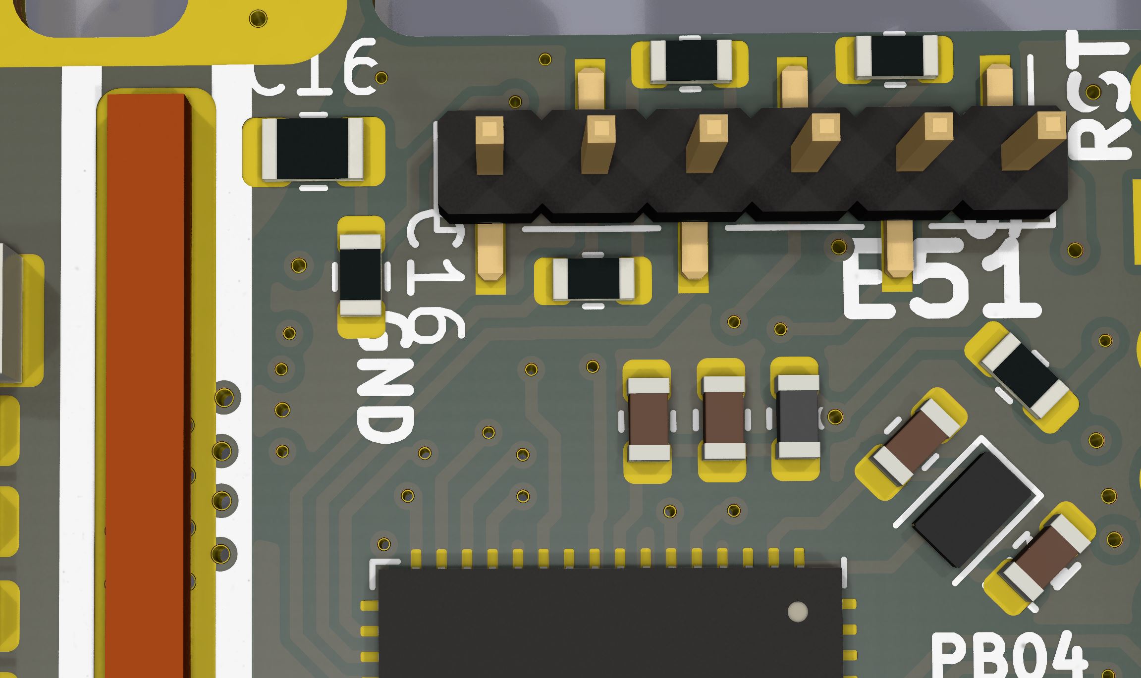
I recently build a hardware solution.

Basically it’s a hysteresis comparator controlling a resistor with Nmos.
You don’t really need PWM, on/off control is fine.
It work nice. The unit parallel with the 24v psu and a blheli_s esc.
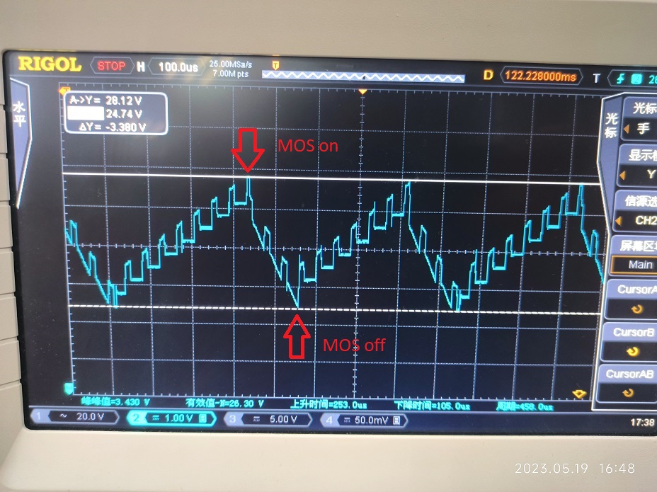
While the esc doing regen it deliver current back in the bus capacitor and produce high voltage.
When it hit the high threshold the MOS is on and clam the voltage until it hit the low threshold.
You can see the bus voltage oscillates back and forth between the two setting voltage.

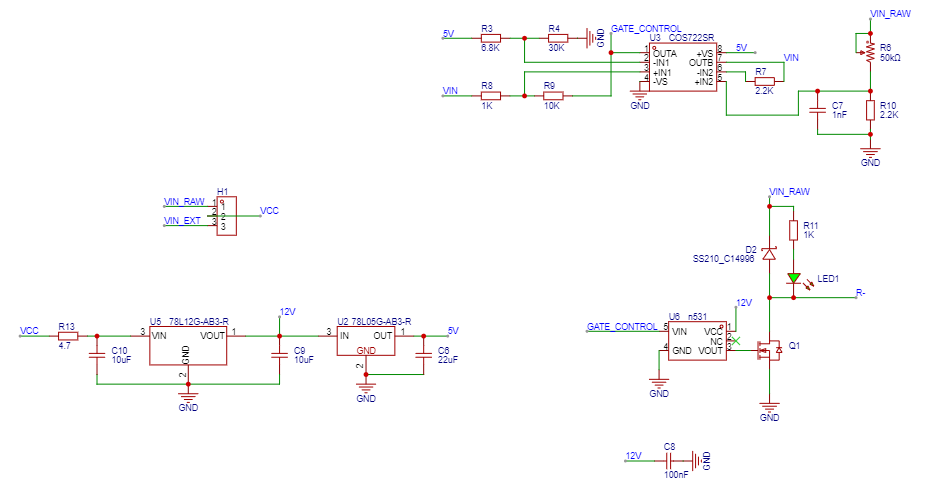
For someone who may want to build one here’s the schematic.
U6 is a low side mos driver and can be replace with UCC27517 or anything you have.
The dissipation resistor connect between VIN_RAW and R-.
1 Like
Hi @runger Thanks for the response… Yeah I did read the analogRead was bad with the G431B-ESC1. I’m hoping the use the PWM pin for PWM output to the IR2104 halfbridge driver. I did see on another post the vbus and temp does work on the G431B-ESC1
Ok, I found te relevant line of code. To read the raw temperature value on the B-G431B-ESC1, use:
float Temp = _readADCVoltageInline(A_TEMPERATURE, currentSense.params);
where currentSense is your initialized LowsideCurrentSense object. Likewise you can use
float VBus = _readADCVoltageInline(A_VBUS, currentSense.params);
VBus = VBus * 10.7711;
to read the bus voltage. I’ll be back home in a week, then I can post the complete conversion to e.g. Celsius.
Hopefully I can get something working and put it into the drivers library for others using the G431B-ESC1
Hi @hbozyq Thanks for that. That’s good to know a simple on/off works. I would have thought using on/off that would introduce noise into the voltage supply/bus? Doesn’t cause any issues?
Definitely yes. It will or will not be a problem dependent on your application. To me it’s fine, no noticeable issue for now.
There are the two parameters should be consider. More bus capacitor will help reducing ripple frequency, lower the high voltage threshold of the hysteresis comparator reduce the ripple amplitude but higher frequency. A compromise configuration Is needed.