Yeah, I guess the electrical zero would have to be aligned exactly for that scenario… sounds very cool!
I’m planning to get high quality ultra-light 110mm high-current (low ohm) motors, and re-solder them in series, that’s definitely going to bring the torque to 50N-m, guaranteed. Although I’m not sure I could find materials for the gears to withstand such stress. Problem is I need to pump 60A continuous current at stall.


Progress on ThorHammer. Estimated maximum continuous torque 1000 N-cm.
Open loop setup:
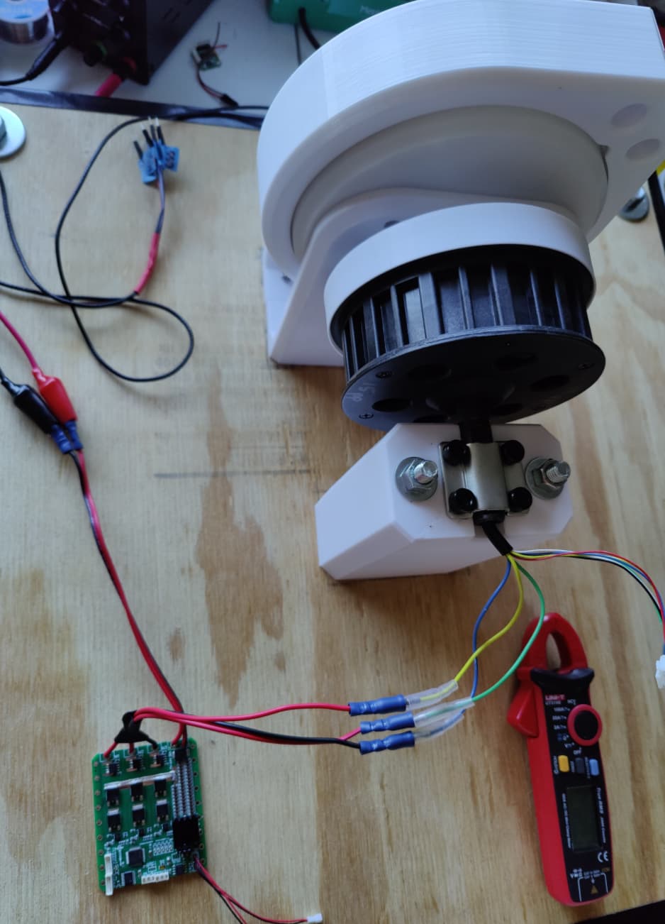
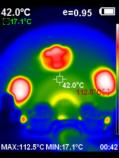
Heat analysis of 15 minutes continues run at 60rpm, 12V / 5A open loop
With ventilation holes, passive cooling, inside the motor coils is 112oC !!! This is only 5A, if we go higher we will melt the solder inside. Forced cooling will be required.
Cables heat analysis

Cables themselves heated up to 35oC, this is insane. I need really thick cables, and this is barely 5A.
PCB heat analysis

Not bad actually, with passive cooling and no heatsinks the PCB behaves better than the cables. However, don’t forget this is 12V / 5A only. If we go higher we will probably see some scary things. I’m still not ready to go full destruction test run until it melts.
Next we do some closed loop with the new cheap chinese angle sensor. Stay tuned.
Cheers,
Valentine
Edit: The full stall torque of the entire system at full load (24V/20A) is actually 10000 N-cm (~= 10 kg-m) however this is impossible due to me using 3D printed gears. If we put 10 kilos on a 1 metre stick it will rip it apart. Therefore I downgraded the torque to 1/10 of the stall torque to account for any dynamic load effects.
5 Likes
Hello ![]()
A little out of the topic, although the use of BLDC for large torque seems to me to be a stone achottement of the technology …
Using epoxy as a coating on the planetary gears improves their behavior. Additive with, a metal, carbon or ceramic filler can be added in the proportion of 4/1 by weight. (with a brush, 0.3-0.5 mm thickness)
(ideal silicat oxide and vacuum tank)
On the other hand, for the sun gear, it is difficult except if switch to a metal gear…
Here, we will do some tests with injected PETG, our material does not permit more than 250°C, the Nylon is not yet accessible to us.
An interesting alternative, from the moment when one does not have to ensure a complete rotary movement, is to use torsion springs directly on the axis of the motor. It’s not linear, but a good challenge. (artificial muscles in prosthesis… and see “I Robot” ![]() )
)
for current holding resistance, it is possible to make PCBs on 4oz ALUMINUM, but 10 x more expensive (~500$ for a 40x40mm), and moreover you have to do the assembly. But 5A to ~30A in continuous mode maybe interesting… For my opinion, it is better to work at high voltage…
Kindly,
Eric
This is my glass filled nylon sun gear, that’s nearly aluminum strength, excellent durability. With the right lubricant it’s perhaps the best trade-off.

3 Likes
NylonG ? I see that need only 255°C ![]()
Could you tell me your nozzle diameter and printing speed?
My (experimental) Dual Planetary Herringbone Gear, interest that don’t need bearing

Best Regards
Eric
1 Like
0.6 extra hardened plated nozzle, 30mm/s
Glass fiber is extremely damaging to the nozzle and feeder. I strongly suggest you commercially print, not at home. Nylon printing requires an entirely custom setup.
1 Like
Hi @Valentine , I have a few questions about Hackjammer (great board btw).
I saw in your design that you added a GD32 next to the STM32 MCU in the schematic - are they pin-compatible? can they just be swapped or there is some work to be done to swap them (GD32 is 7$ cheaper I think on jlcpcb)?
Is the voltage limitation for the board (7-24V) due to the fact that you designed around basic parts when available (I saw some caps are lower voltage) or there is more to it?
I am thinking of adapting it a little bit to be cheaper and extensible (current sense and can modules as extension boards).
Did you test the board at 24V high amp power?
Thank you.
Yes, fully pin compatible. I recommend you only replace the component during order time directly from the BOM and do not replace in the schematics, you will break all routing, unless you are brave enough and want to fully reroute.
Yes, and also cheaper. Strictly speaking the board could take up to 40V but you need to use superior components which are a lot more expensive.
You want to break out the CANBus and current sense separately? That will require a complete rework. You can try and see what works in your case. I also highly recommend you replace the LDO with a buck converter, else the LDO will blow up at anything higher than 12V without a heatsink.
I tested up to 5A. The LDO overheated and I had to add a heatsink. I’m really busy these days with other projects. Also summer is coming, I’m going on a long vacation.
Let us know what you find out.
Cheers,
Valentine
1 Like
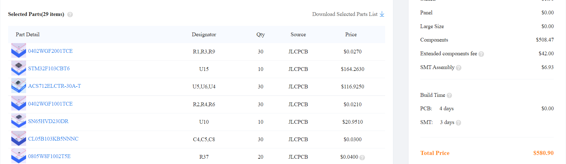
Did you run into similar price points when you had your boards manufactured? I am aware of the crazy prices of silicon these days, but this is bananas!
Haha maybe I am just a bit envious of how cheap the Mosquito boards are…
Yes, it is. That’s why everyone is hunkering down and just waiting for the bad wind to blow over. Is it for 10 boards? I see 10 MCUs so I assume 10 boards. You can try 5PCB and 2 SMD-ed boards. This will be around $65/board but the total will be a lot less.
You can try replacing the STM32 with GD32, but other than that you won’t find too many easy and cheap replacements. May be skip the CANBus components if you don’t need CAN.
Don’t forget the Mosquito is 100 times smaller, and using an integrated driver with a smaller MCU. Getting $58 per board is actually cheap, believe me. The original JackHammer was about $100/board, using the nice original Infineon 300A MOSFETs.
Cheers,
Valentine
Replace the MCU with part number C77979, this will cut the price by $7 per board, or cut $70 for 10.
I took another stab at it today, and with the GD knockoff alongside the jettison of the two CAN IC’s I can either get 5 boards at $50/board or 2 boards at $75/board.
That isn’t too terrible.
Also, since I need a SWD debugger, could I just use the daughterboard of the B-G431B-ESC1 I already have? It can be snapped off to expose the SWD pins.
Yes, if you manage to properly break it off and solder leads. That board is really delicate.
Buy the 5 and sell the spares here ![]()
1 Like
That can definitely be done - but I feel that is more @Valentine 's choice than mine, as it is his board.
I am not sure how he feels about getting money involved with his designs.
Board is public domain. Unless you plan on selling 10000 boards a month, in which case you may have a real problem because the board will need some changes to make it end-product-able.
I hereby give an official release from me to anyone to make and sell as many as you want. Also, as I said, the LDO needs to be replaced with a buck, so caveat emptor. I take no responsibility if anyone gets hurt by the board.
Cheers,
Valentine
Any thoughts about using this with 36V? Everything looks like it should support the voltage, and I don’t need a huge number of amps. My project already has a dedicated 36V power supply so I shouldn’t have an issue with the concern you raised about anything above 12VDC above. https://community.simplefoc.com/t/project-sanity-check-with-mp6540-optical-encoder-simplefoc/960