EVTOL system - brushless servo module with UAVCAN

Now Evtol flies on PWM, in some cases we have 11 separate devices for each of which you need to install signal lines physically through the wings, fuselage, detachable connections …

Also, turning nodes limit the resource of a large bundle of wires, if you use sliprings, this will definitely limit the use of analog control protocols.

In addition, if the signal lines are not groud-shielded, then sometimes interference will appear, in the form of twitches, especially when the carbon propeller rotates over the blades at a some frequency that produce electrostatic.

In this case, it is much more convenient, in my opinion, to extend one CAN bus to control many devices, and also get feedback. + control accuracy is limited only by the capabilities of the MCU that really cool.

And the ability to configure each device separately.
My ultimate goal is to move from PWM to CANUAV.

I can buy a ready-made drive from Hitec, but here’s why I won’t do it:

  1. classic gear engagement
  • inability to work with dynamic loads
  • low resource, less than 50 hours of work in my use-case
  • 1.5 - 3 teeth are involved in the engagement of gears
  1. changes angular velocity with temperature drift
  • because a large specific load on the tooth, a grease is needed that slows down operation at low temperatures (without feedback, the autopilot does not know at what angle the mechanics is turned, which leads to a crash in the worst case)
  1. no feedback
  • need to know the current position
  • power
  1. no holding torque control to adjust propeller damping during operation

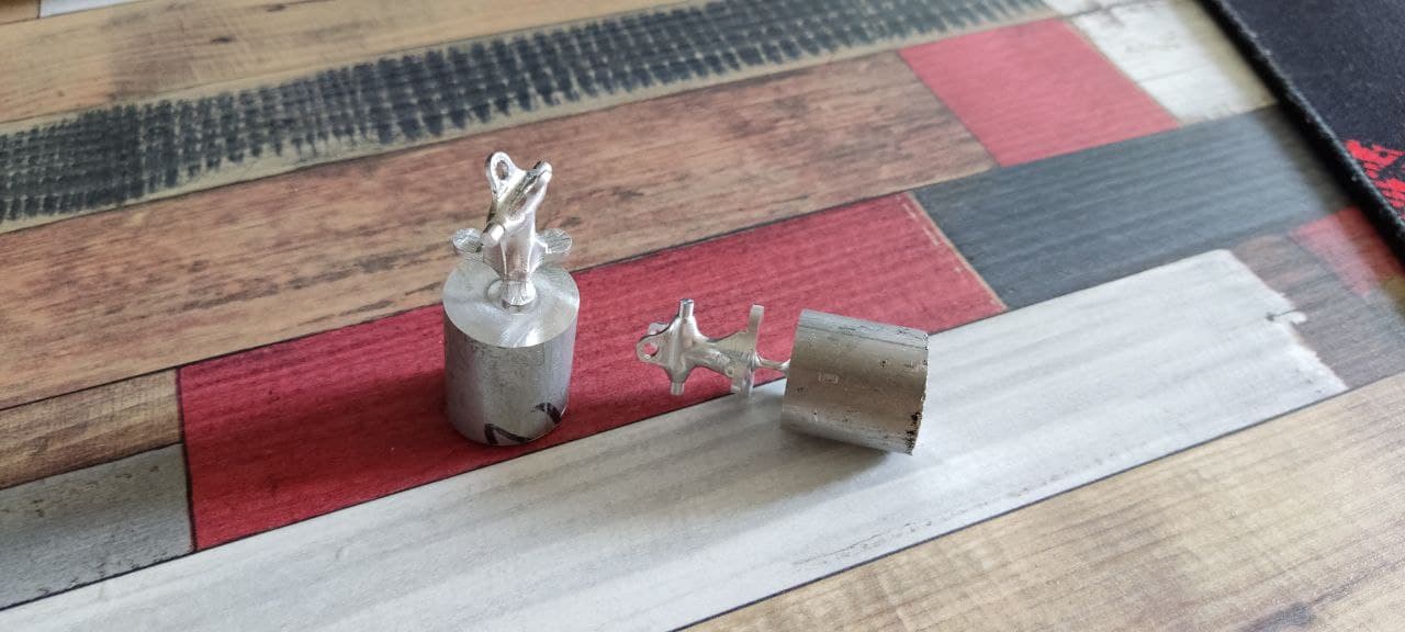
So I started to develop my own wave drive, I have a good knowledge of mechanical engineering, I can make my high precision metal parts with 4 axis milling machine, the machining accuracy that I can now achieve > 0.005mm. It is important that for me it is cheap, because. I do it myself.

Now, thanks to you guys, I saw that the electrical part is possible, its size is not as important as the ability to make boards of its own shape, this is important when designing eVthol, so I can’t use ready-made parts because I don’t like their form factor, I just can’t arrange it like this as I need.

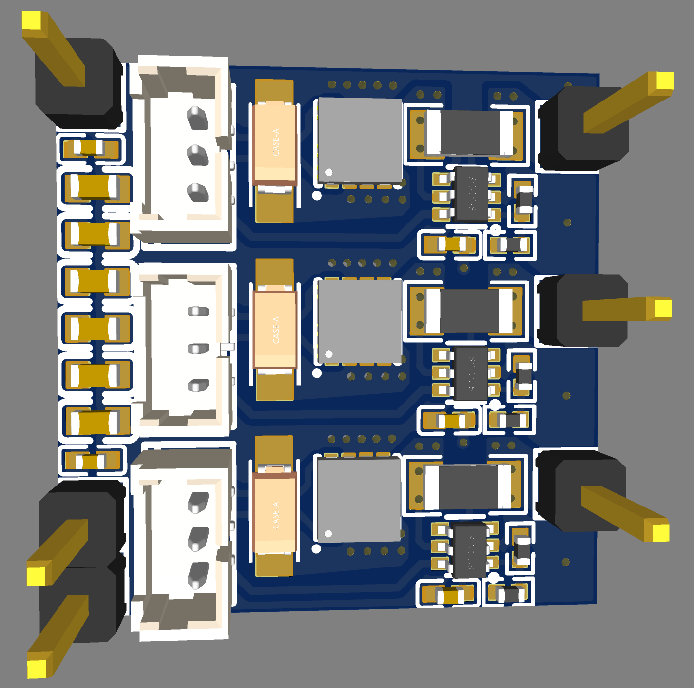
I don’t need a ready-made driver of a small size, because I still have to redo it, I need an understanding of what components are needed and a schematic diagram of their connection, because i never worked with it :slight_smile:

now i see it like this

  • metal micro wave reducer 1:30 (I will develop and make it myself) after i want to do it in mass plastic production for community
  • FOC motor control with feedback (now I’m waiting for AS5047P)
  • position control of wave reducer by AS5600
  • consumption no more than 1A typical now I see 0.2A ( bldc 2204 15 Ohm per phase, now i have 40 Ohm) After i want create own cheap design by ferromagnetic SLM printing
  • voltage 16 * 24 V (this is the battery operating range in flight)
  • communication via СAN UAV but for first test PWM
    GitHub - 107-systems/107-Arduino-Cyphal: Arduino library for providing a convenient C++ interface for accessing OpenCyphal.
  • MCU ? now i have blue pill with original F103C8 for experiment but esp is complitelly cheap and better?
1 Like

It certainly sounds like a very cool project! If it is ok, I will split it into it’s own thread, since I feel we’re digressing a bit from the topic of the Hot Dog :grinning_face_with_smiling_eyes:

It would work with an ESP32, probably, but you would have to count the pins needed carefully… ESP32 is a bit short on pins for these types of things.
It would certainly work with an STM32 MCU. Personally I’d pick a more modern one than the F103, but I think it could work with that one.

1 Like

Now I have to start reading about UAVCAN which isn’t really CAN or for only UAV.

A board like that would be 40mm X 40mm. If you do not need current sensing, it could go down to 30 x 40.

Why do you need a second sensor? You have the reducer ratio and the motor sensor. Unless your reducer skips teeth, at which point I’d quit the reducer idea.

Also, small wave reducer is really, really hard to manufacture, believe me, I’ve tried myself. Just to make sure, we are talking strain wave (harmonic) reducer, correct?

I’m not telling you what to do, just my observer’s opinion. Don’t listen to me.

Cheers,
Valentine

1 Like

Found this article. Would be interesting to learn more about the UAVCAM pwm adaptor board and incorporate that into a motor driver (esc) board that works with simplefoc.

1 Like

UAV CAN has many aplication other than UAV. How i uderstand it benefit light weight, hight level abstraction and no need bus master devices.

of course, this can be done through end-stop and initial position calibration before launch, but there are situations with restarting modules in flight, I would like to avoid re-calibration in flight, so I think that a second encoder is needed. Maybe I’m wrong, but intuitively I understand that it is worth knowing the current position of the mechanics relative to the wing.
I like the solution with a CAN to PWM adapter and simpleFOC control via PWM, most likely the first prototype will be implemented this way, but the ultimate goal is to integrate the communication UAVCAN protocol into simpleFOC, especially since now you can compile firmware with it, but you need to understand the communication protocol itself, I I’m dealing with this now.
I have time before spring, so I’m not in a hurry, I don’t like to fly in winter.

Sorry, i misled you, somitime like this in smaller size and some modifications

I understand it
I have experience in milling

Here processes of milling ESC radiator

Zero baclash gears in small size, module 0.65 mm
they are made with a ball cutter 0.5 mm in diameter

Valentine If you want to try again, I can make a prototype for you for free.

Wow these guys are next to me at 10 km O_o
I’m going to talk to them one of these days
Though their boards are very expensive for pwm $400

I work with compromises every day to decide which evil is the less evil for my project, so any opinions are welcome.

Thats way too complicated, why not use canbus transceiver directly?

My design needs planetary gears. Can you cut planetary gears up to 100mm diameter?

use canbus transceiver directly is preferably and is the ultimate goal.

Yep need to see sldprt files or IGES I use 2020 version SolidWorks
Problems can only arise with sun gear but need to look at the files to say for sure

I use 2020 SolidWorks, and could send you directly the parts files. Also, I am reasonably advanced in SolidWorks and could redesign everything depending on your manufacturing workflow, including first prototyping the design in-house before cutting, based on your CNC capabilities. Please DM/PM me for details, this is outside the scope of the current discussion. The sun gear is fairly large and teeth are well defined as generic spur.

I created a sample power stage of a small driver that theoretically goes to 24V / 10A continuous current, with direct control from an MCU with 3.3v pin PWM without a driver, with inline current sensing, and sent it for manufacturing, all components in stock. If it is successful, I’ll post the schematics. Size is 20mm x 20mm. I’m very busy, and it will take up to two weeks until the driver gets fabricated and shipped, these days, it takes forever. Then I have to test.

1 Like

Looks great and perfect for robotic applications
Separate power board from MCU ideal layout for easy heat dissipation

Perfect for us to control ground antenna tracker

Please keep up to date with test results.
What is the estimated cost?

In a batch over 10 boards if made individually and fully soldered, around $10 per board. I may need to add a driver which will increase a bit.

The last servo I bought from “Blue Bird” cost $60 and because of its failure I crashed a $6k vehicle :slight_smile:
Now I will do a lot of bench tests on the ground to failure)
And no longer buy RC servos.

I’ve been thinking very long about this, and slowly coming to the realization that there are plenty of MOSFETs and current sensors, and all kinds of power boards, but what’s the biggest gap here is a cheap, SimpleFOC-able intelligent driver. I very much dislike the word “intelligent” but it may be applicable in this sense. This is what I came up with, let’s call it Driver DOG!, it combines G031 with 12-volt drivers, current sense, two SPI ports, UART, SWD for programming, an NTC thermistor to measure over-temperature, and an LED to do simple debugging signaling.

You could load SimpleFOC and run in PWM3 with SPI sensor, or I2C sensor, or Serial, and have another SPI for CANBUS or whatever else, you could attach also instead of SPI sensor three halls, whatever you want, the pins are exposed to the left.

I welcome any inputs on this. The only limitation is that you can control only up to 12V MOSFETs with that driver. Controlling high voltage MOSFETs will require different drivers, and PWM6 control, which will lose one of the SPI channels, so no CANBUS. The G031 is really small and the pins don’t allow that, so perhaps you could control only via serial or I2C, or PWM for a high-voltage iteration of that idea.

I’m planning to combine this with the Nano DOG and see if it works.

Size of the driver is 20mm x 20mm, all components are in stock. Pretty cheap, too.

@Andrey_Sabadash , something interesting, the MOSFET drivers I used are specifically designed for UAV.

1 Like

Looks great!
I will not tire of repeating this, I do not understand how you make boards so quickly.

12 volts is normal, now i use a step down converter anyway

most likely it will not get warm, since the current to the motor will be very small, while I am experimenting with the resistance of the motor, so I can’t give exact values

I moved a little on the mechanics, generated a concept

cycloidal

Most likely it will be metal, two-stage
but I’ll try to do this first to check the reality of manufacturing by milling

I tried to make it on a 3D printer, it’s almost impossible to do it well XD

And it should be twice as small in size

Three advanced degrees and thirty years of experience would probably explain this.

1 Like

I have a box of failed cycloids. I keep it to remind me never again to try this.

I even developed a parametrized SolidWorks script where I put the required parameters and it generated all parts automatically, with tolerances and everything. Then, when I tried to make it work, things went sideways very quickly.

1 Like

If you need a high ratio, and machinable reduction gear which is guaranteed to work, you need to look into split planetary epicyclic gear. It’s a very interesting hybrid between cycloid, strain wave, and planetary drive. On a 3D printer, it delivers good manufacturability, near-zero backlash and very resistant to small errors.

You could achieve 1:500 reduction ratio with split epicyclic gear.

1 Like
2 Likes

Me neither, it’s simply amazing!

It’s hard. I’ve also tried…

:rofl: :joy: :rofl: :rofl: I have such a box too! I’ve also more or less given up on this. I can get them working with about 10-15cm diameter, but that’s 3 times the size I would like to achieve.

My conclusion was that they have to be metal, and I need a CNC mill. But @Andrey_Sabadash has a CNC setup, so I think he will make it work!

You’ve given me yet another thing to look into! Thank you for this pointer, that’s super interesting!