ESP32-S2 STEP/DIR Servo

Hello, im currently trying my luck on a diy board to use simplefoc on a 3D Printer Extruder.
Its a special design, that needs higher rpm than a stepper can provide with enough torque.
Since there is this shitty MCU shortage, i will try my luck with the ESP32.
JLCPCB has it on stock, its aviable in a small package and it has plenty of power. + its cheap af <2€.
But i have some questions, if someone has the time to help :grinning::

  1. I found this IC/Power Switch, and controlled the datasheet, and i think 3 of them would be an awesome solution for a BLDC driver.
    https://datasheet.lcsc.com/lcsc/2008121206_uPI-Semiconductor-UP9636PQMY_C696064.pdf
    Did i miss something, or did i find the perfect driver for under 25V application?
  2. Since i need more speed than a stepper, i dont need a high precision, like at least 30CPR, but does simplefoc work reliable with such a low resolution, using the step/dir listener.

This design needs a hollow shaft, so i cant use a magnetic encoder like AS5600, + i want it to be small and light, so the AMT103 is no option.
My idea was to make my own reflective incremental encoder with 2x GP2S60A.https://www.mouser.de/datasheet/2/365/gp2s60_e-106.pdf
30-60 CPR on a 35mm wheel should be doable i guess. :wink:

Thanks

Hey just a heads up, the esp32 S2 isn’t supported by simplefoc because the motor controll pwm function is missing on it.
Only the normal esp32 will work with simplefoc as far as I know.

At least it was this way last time I looked into it, but that could have changed so do your own research on it.

Also the MOSFET ic looks interesting but i wouldn’t implement it if i could because it’s hard to hand solder this type of ic, it’s certainly doable but i wouldn’t do it unless there is nothing with a better footprint / package.

If you find the amt encoder to heavy maybe look into a AS encoder that works with magnetic rings.

The driver seems in stock, so if I were you, I’d definitely first build a very small dev board with one driver and all extra components around, to test the module before I commit to a full-blown solution.

As @Franz_Schmidt noted, not all ESP32 are created equal. If I were you, I’d probably stay with tried and true MCUs. STM32F103 is still available at JLC, on and off, albeit at inflated prices. Keep watching and they keep restocking about 100 at a time. You could also try the Gigadevice clones, if you feel like it. They are also in stock, though I personally frown at clones, but these days all bets are off. Extreme case you could even order a small nucleo and build a footprint to pop a nucleo in. Or order a bluepill and pop into a footprint. This is not for production I assume so its fine. Teensy would be a fine choice, too.

There are ring encoders, however, you may need to ask someone on this board familiar with them, since I’ve not worked with those. I’ve worked with such an off-shelf encoder

However it was not for SimpleFOC but a completely different project. And it’s not cheap either.

Hmmm… That’s a rabbit hole. Alice would be happy. Say hi to the hookah-smoking caterpillar. Come back and report.

I’d definitely first draw the board and post it here and ask for people to review before I order.

Cheers,
Valentine

Hey,

As others have noted, I would prefer the older ESP32s to the S2 models. They should also be available… the ESP32-PICO-D4 is a nice one. We actually have code on the dev branch supporting the S2s using their LED-PWM driver, but the older ESPs have a dedicated MPWM driver for motor control, it’s much better.

The 30-60 CPR will be very low for FOC control. I doubt it will work well. I’d also not recommend making your own encoder. Possible, but trickier than you might expect. Definitely not the fast track to getting good results.

Maybe take a look at the MagAlpha magnetic sensors? A MA732 can also be mounted to the side of the magnet, and there are also magnets with holes in the middle… you can get some motors with the hollow magnet already integrated into the hollow shaft, maybe they would suit your purpose? When I get back to my workshop next week I can post some pictures / serial numbers.

The driver looks pretty nice - the datasheet is a bit low on information regarding the timings, but it looks to me like it would work…

If you do decide to use the S2, I think it should work with this driver, since the driver only needs one PWM input.

Thanks guys.
I already designed the PCB, i also added 2 hall sensors, and an AS5600 to try different versions.
JLCPCB has also the ESP32-D0WDQ6 in stock, which i already tried in openloop and a ln298 driver.
So i will change that.
The QFN-Package is no problem, bc i dont solder it myself.
The MA732 looks interesting, thx.
Sadly its nearly impossible to get, and kinda expensive.
But i made the pcb in a way that i can mount different sensors in the middle of the pcb.
Sry for the messy schematic. :see_no_evil:
Schematic_Encoder AB ESP32_D0WDQ6_2021-11-07
PCB_PCB_Encoder AB copy copy_2021-11-07

Sry for doubleposting, but i found the AEDR-8300
https://www.mouser.it/datasheet/2/678/AVGOS05599_1-2574607.pdf
A really simple to use optical encoder, which would allow a much better resolution and a simple codewheel.

My take

image

Are the 12V all on the same rail? If that’s the case then you can ignore the 12v no capacitors at all, and perhaps consider separating the rails, then adding some? I have a lot more comments but they won’t fit here. Also the Holtek LDOs aren’t nearly powerful enough to run the ESP, you are looking at something at least 1A draw with a big tantalum capacitor. Also the power surges and ringing back from the MOSFETS will kill any LDO and fry your ESP. Check this thread to see what are you up against:

https://community.simplefoc.com/t/esp32-s-ai-thinker-dev-board-schematics-pcb/1293

@Valentine Just a question, maybe a bit off topic. I want to run 4 esp32 of a 3.3v rail that’s good to about 3A (buck converter from 24v down to 3.3) do you think that’s enough because i couldn’t find much for the maximum esp32 power draw.

Thx for your time,
I guess the LDO were a bit optimistic^^, i replaced the 5V one with an MT2492 (Buck), and hooked the 3V3 un the 5V output.
I wont use the ESP32 wireless modem, so the raw current draw of the ESP will be about 20mA according to the datasheet.
@runger
You wrote that the LED PWM would work, so i will give it a try, because the S2 dont need a separate chip for usb programming. See tinyS2
I think i have to provide more info:

  • voltage should be 12V, one rail
  • it just has to drive a 2805 (35mm dia.) Gimbal Motor, about 0.5-0.8 A.
  • I dont need more than 2000 rpm (probably not more than 1000).
  • i just need an accuracy about 30 CPR, but more is always better.
  • i thought i could make a encoder with small magnets and 2 hall sensors, i tried it int the meantime, it didnt work well, so im removing them.
  • Maybe i dont need closed loop at all^^
  • As mentioned the AEDR-8300 could be easy to use as encoder, so reserved it a place on the pcb, if both GP2S60A wont work.

I think i dont need more capacity on the 12V rail, since its more or less a gimbal controller for just 1 motor, which never have big capacitors. Even the B-G431B-ESC1 has just about 200uf.
Also snubber can be omitted for such low power i guess.

The ESP32 S2 circuit is drawn after this:
https://unexpectedmaker.com/tinys2
I just dont use the antenna circuit and battery charger.
I cleaned and updated the schematic:
Schematic_Encoder AB ESP32_2021-11-08

Problem is not the steady-state use, problem is boot. You have no control there. At boot the MCU draws a lot more power, in a surge that exceeds the conventional capacitors current and ripple, according to some sources enough to even saturate an USB 5V which is 2A. Hence the tantalum capacitor. Else you will end up in a perpetual reboot, where the MCU boots, browns-out, and reboots, ad nauseum. And you have all these auxiliary sensors which draw power, some quite a lot.
As I said you may really want to see what others have done about this, but that’s up to you, I guess part of the learning experience. I am very interested in the progress.

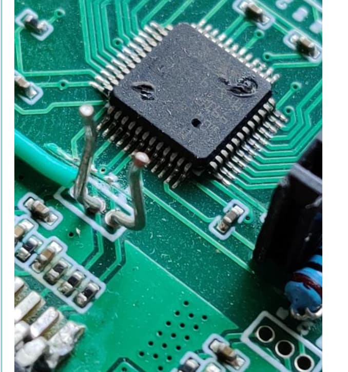
I can show you an MCU I fried with an LDO without a snubber and not even load connected. It went so hot it glowed red and burst in my face. Luckily I wear safety goggles all the time.

For the proper way of building the MCU power supply please check this thread

Except in your case you also need the tantalum capacitor boot surge buffer.

Come back and report, and please wear safety equipment when testing this.

It is, as long as you buffer sufficiently.

Does that footprint happen to be an M5Stack size? 5cm x 5cm? I’m interested in working with that footprint. I just started work on an ‘open core’ for ESP32devC