Encoder reading using SPI port (Biss-C)

One note; I try change motor and encoder just to verify and I notife that if I run same code in Arduino IDE it works, but not in platformio, I use same version of SimpleFoc as well.

[env:genericSTM32F405RG]
platform = ststm32
board = genericSTM32F405RG
board_build.mcu = STM32F405RG
board_build.core = stm32
board_build.f_cpu = 168000000L
upload_protocol = stlink
framework = arduino
lib_deps = 
	stm32duino/STM32duino FreeRTOS@^10.3.2
	askuric/Simple FOC@2.3.0
lib_archive = false
monitor_speed = 115200
build_flags = -Os
build_type = debug
debug_tool = stlink
In platformIO you need the option lib_archive = false in your platformio.ini… did you add it?

On a magnetic sensor, the interference can also be magnetic in nature - in this case you can check by moving the magnet further away from the motor. 5mm more distance will make a big difference to the field strength. You can also reduce the air-gap between sensor and magnet, or use a stronger magnet… that’s if the sensor uses a magnet, of course.
Capacitative sensors don’t usually have interference problems with the motor magnets, and nor do optical or physical encoders.

Or if the interference is electrical in nature, maybe it is happening already on the PCB, and not in the cables…

You are right, once I put lib_archive = true it works :slight_smile: the change between platformio now is that motor is doing a high pitch sound when moving, this does not happen in Arduino IDE, what can be the cause? code is same.

Hi,

Sorry, it should be lib_archive = false ! My thoughts are not 100% here, I think!

Acually I had false before and it did not work, once I put true it work fine just the high pitch sound when motor moves :smiley:

Yeah, that’s because it is using the generic PWM, it will never work well in this mode…

Unfortunately you need lib_archive = false, and need to investigate why it is not working… with the genericSTM32F405RG board definition there can be many reasons, maybe you need a different clock setup function for example…

1 Like

Hi,

I will dig into it and see, just asked incase anyone else had same issue.

Thank you @runger for your awesome support!

I tried all settings with platformio for STM32F405RG and can’t get the encoder to work, it always read 0, all works great when build in Arduino IDE using same code :confused:

Encoder encoder = Encoder(PA11, PA12, 8192);
// channel A and B callbacks
void doA(){encoder .handleA();}
void doB(){encoder .handleB();}

encoder.init();
encoder.enableInterrupts(doA, doB); 

Anyone had this issue?

platformio.ini

[env:genericSTM32F405RG]
platform = ststm32
board = genericSTM32F405RG
board_build.mcu = STM32F405RG
board_build.core = stm32
board_build.f_cpu = 168000000L
upload_protocol = stlink
framework = arduino
lib_deps = 
	stm32duino/STM32duino FreeRTOS@^10.3.2
	askuric/Simple FOC@^2.2.2
lib_archive = false
monitor_speed = 115200
build_type = debug
debug_tool = stlink

Hi,

I still find that some issue regarding position look below, jumps from 33019-49037 and back to 32886, so something is still wrong with data, I notice the first byte jumps only between 34 and 35 in a full turn, maybe half turn indicator ?

@runger halp :smiley:

uint16_t rawval16 = ((buff[0]&0x07)<<13) | (buff[1]<<5) | ((buff[2]&0xF8)>>3);

34 8 F5 AA rawval16_: 33054
34 7 DD E4 rawval16_: 33019
35 FC 6F FA rawval16_: 49037
35 F4 AD C0 rawval16_: 48789
35 EF 53 AC rawval16_: 48618
35 F2 13 86 rawval16_: 48706
35 F9 47 8C rawval16_: 48936
35 FF EF A4 rawval16_: 49149
34 3 B3 FE rawval16_: 32886
34 6 5D 9C rawval16_: 32971
34 6 AB C4 rawval16_: 32981
34 6 63 98 rawval16_: 32972
34 6 59 AC rawval16_: 32971
34 6 57 E4 rawval16_: 32970
34 6 55 FC rawval16_: 32970
34 6 59 AC rawval16_: 32971
34 6 57 E4 rawval16_: 32970

I notice second byte restart counting when it changes from 35 to 34 (motorn turn half turn)

35 F9 29 DA rawval16_: 6981
34 8 A3 D0 rawval16_: 6676

Ps regarding platformio I had to add this to get it working if someone else have any issue :slight_smile:

build_flags = -w
   -D HAL_SDRAM_MODULE_ENABLED
   -D HAL_MDMA_MODULE_ENABLED
   -D HAL_DMA_MODULE_ENABLED
   -D INSTRUCTION_CACHE_ENABLE

A little confused because 15 days ago you showed what looked like perfect angles from 0 to 6.2. Why wasn’t that having the same problems?

1 Like

I fully understand I was was travelling with work and continued tests :slight_smile: so still notice the issue after a few tests.

I also found this: page 8

I think it’s just the first byte that needs some adjustment but not sure what bits that are used :confused:

Binary Output of full turn of encoder:

byte0: 00110101 - byte1: 11100100 - byte2: 11011101 - byte3: 10100100
byte0: 00110101 - byte1: 11100101 - byte2: 00010111 - byte3: 10110000
byte0: 00110101 - byte1: 11101110 - byte2: 01010011 - byte3: 11111100
byte0: 00110101 - byte1: 11111111 - byte2: 11110101 - byte3: 10011010
byte0: 00110100 - byte1: 00000111 - byte2: 11100001 - byte3: 11111000
byte0: 00110100 - byte1: 00010000 - byte2: 01100011 - byte3: 11001110
byte0: 00110100 - byte1: 00011100 - byte2: 01010111 - byte3: 11100000
byte0: 00110100 - byte1: 00101000 - byte2: 00011011 - byte3: 10101100
byte0: 00110100 - byte1: 00110011 - byte2: 00010011 - byte3: 10011000
byte0: 00110100 - byte1: 00111101 - byte2: 10000101 - byte3: 10101010
byte0: 00110100 - byte1: 01000111 - byte2: 10101001 - byte3: 11111010
byte0: 00110100 - byte1: 01001110 - byte2: 11101111 - byte3: 10001000
byte0: 00110100 - byte1: 01010101 - byte2: 11011111 - byte3: 10010000
byte0: 00110100 - byte1: 01100101 - byte2: 01110011 - byte3: 10100110
byte0: 00110100 - byte1: 01101101 - byte2: 11110001 - byte3: 10001000
byte0: 00110100 - byte1: 01101110 - byte2: 00111001 - byte3: 10100010
byte0: 00110100 - byte1: 01110110 - byte2: 01000101 - byte3: 10001000
byte0: 00110100 - byte1: 01111101 - byte2: 01110001 - byte3: 10011100
byte0: 00110100 - byte1: 10000100 - byte2: 01111001 - byte3: 11101010
byte0: 00110100 - byte1: 10001011 - byte2: 10011111 - byte3: 11010000
byte0: 00110100 - byte1: 10010101 - byte2: 11000001 - byte3: 10000010
byte0: 00110100 - byte1: 10100001 - byte2: 01110111 - byte3: 11000110
byte0: 00110100 - byte1: 10101110 - byte2: 11101011 - byte3: 11011100
byte0: 00110100 - byte1: 10111100 - byte2: 01010001 - byte3: 11011010
byte0: 00110100 - byte1: 11000110 - byte2: 10101111 - byte3: 11101000
byte0: 00110100 - byte1: 11010011 - byte2: 01110101 - byte3: 11001010
byte0: 00110100 - byte1: 11100010 - byte2: 00100101 - byte3: 10001100
byte0: 00110100 - byte1: 11101101 - byte2: 10011001 - byte3: 10011100
byte0: 00110100 - byte1: 11111100 - byte2: 11001101 - byte3: 10010010
byte0: 00110101 - byte1: 00001001 - byte2: 10100001 - byte3: 11001010
byte0: 00110101 - byte1: 00011001 - byte2: 00101101 - byte3: 10001110
byte0: 00110101 - byte1: 00101010 - byte2: 00110001 - byte3: 10101010
byte0: 00110101 - byte1: 00101001 - byte2: 11101011 - byte3: 11011110
byte0: 00110101 - byte1: 00101001 - byte2: 11011111 - byte3: 10100010
byte0: 00110101 - byte1: 00110100 - byte2: 00101011 - byte3: 11011100
byte0: 00110101 - byte1: 01000000 - byte2: 00100011 - byte3: 11000010
byte0: 00110101 - byte1: 01001100 - byte2: 11010001 - byte3: 11111000
byte0: 00110101 - byte1: 01010111 - byte2: 00010001 - byte3: 10010000
byte0: 00110101 - byte1: 01100000 - byte2: 00110011 - byte3: 11111100
byte0: 00110101 - byte1: 01101001 - byte2: 00000111 - byte3: 11001110
byte0: 00110101 - byte1: 01110110 - byte2: 00011001 - byte3: 11011000
byte0: 00110101 - byte1: 10000000 - byte2: 11101011 - byte3: 10000010
byte0: 00110101 - byte1: 10001010 - byte2: 00010101 - byte3: 10000010
byte0: 00110101 - byte1: 10010011 - byte2: 11001101 - byte3: 11101010
byte0: 00110101 - byte1: 10011100 - byte2: 11101101 - byte3: 11000100
byte0: 00110101 - byte1: 10101010 - byte2: 00010011 - byte3: 11010010
byte0: 00110101 - byte1: 10110011 - byte2: 01001011 - byte3: 10010010
byte0: 00110101 - byte1: 10111100 - byte2: 01111001 - byte3: 11100010
byte0: 00110101 - byte1: 11000101 - byte2: 11001011 - byte3: 11100010
byte0: 00110101 - byte1: 11001111 - byte2: 01111011 - byte3: 10111110
byte0: 00110101 - byte1: 11011010 - byte2: 01011011 - byte3: 10010100
byte0: 00110101 - byte1: 11011101 - byte2: 00111001 - byte3: 10101000
byte0: 00110101 - byte1: 11011101 - byte2: 00110111 - byte3: 11100000
byte0: 00110101 - byte1: 11011101 - byte2: 00111001 - byte3: 10101000

Only last bit in byte1 change from 00110100 to 00110101 during a full rotation.

Angle never goes from 0-2PI during a full turn check below:

angle_: 4.70
angle_: 4.70
angle_: 4.70
angle_: 4.71
angle_: 3.17
angle_: 3.18
angle_: 3.21
angle_: 3.24
angle_: 3.27
angle_: 3.29
angle_: 3.30
angle_: 3.32
angle_: 3.34
angle_: 3.36
angle_: 3.38
angle_: 3.39
angle_: 3.41
angle_: 3.44
angle_: 3.47
angle_: 3.48
angle_: 3.48
angle_: 3.48
angle_: 3.48
angle_: 3.50
angle_: 3.54
angle_: 3.56
angle_: 3.57
angle_: 3.59
angle_: 3.61
angle_: 3.62
angle_: 3.64
angle_: 3.65
angle_: 3.67
angle_: 3.69
angle_: 3.72
angle_: 3.75
angle_: 3.78
angle_: 3.81
angle_: 3.85
angle_: 3.87
angle_: 3.89
angle_: 3.90
angle_: 3.92
angle_: 3.95
angle_: 3.97
angle_: 4.00
angle_: 4.02
angle_: 4.04
angle_: 4.05
angle_: 4.07
angle_: 4.10
angle_: 4.12
angle_: 4.14
angle_: 4.16
angle_: 4.18
angle_: 4.21
angle_: 4.21
angle_: 4.21
angle_: 4.22
angle_: 4.24
angle_: 4.26
angle_: 4.28
angle_: 4.30
angle_: 4.32
angle_: 4.33
angle_: 4.35
angle_: 4.35
angle_: 4.36
angle_: 4.37
angle_: 4.38
angle_: 4.40
angle_: 4.41
angle_: 4.44
angle_: 4.45
angle_: 4.47
angle_: 4.49
angle_: 4.51
angle_: 4.54
angle_: 4.56
angle_: 4.60
angle_: 4.62
angle_: 4.64
angle_: 4.66
angle_: 4.68
angle_: 4.70
angle_: 3.15
angle_: 3.18
angle_: 3.18
angle_: 3.22
angle_: 3.24
angle_: 3.24
angle_: 3.24
angle_: 3.24
angle_: 3.24
angle_: 3.24

update:

I just had to add 3.0us between SPI reading and it works like a sharm :slight_smile:

3 Likes

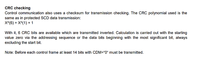
Anyone know how to calculate crc? :slight_smile:

Page 9 of your datasheet:

Hi!

Seems quite complex, any idea how to implement this?

I found this document from RLS:

https://www.rls.si/en/fileuploader/download/download/?d=0&file=custom%2Fupload%2FApplication-note-Decoding-the-BiSS-information.pdf

u8 tableCRC6[64] = {
	0x00, 0x03, 0x06, 0x05, 0x0C, 0x0F, 0x0A, 0x09,
	0x18, 0x1B, 0x1E, 0x1D, 0x14, 0x17, 0x12, 0x11,
	0x30, 0x33, 0x36, 0x35, 0x3C, 0x3F, 0x3A, 0x39,
	0x28, 0x2B, 0x2E, 0x2D, 0x24, 0x27, 0x22, 0x21,
	0x23, 0x20, 0x25, 0x26, 0x2F, 0x2C, 0x29, 0x2A,
	0x3B, 0x38, 0x3D, 0x3E, 0x37, 0x34, 0x31, 0x32,
	0x13, 0x10, 0x15, 0x16, 0x1F, 0x1C, 0x19, 0x1A,
	0x0B, 0x08, 0x0D, 0x0E, 0x07, 0x04, 0x01, 0x02};
	
u8 crcBiSS(u32 data)
{
	u8 crc;
	u32 tmp
	tmp = (data >> 30) & 0x00000003;
	crc = ((data >> 24) & 0x0000003F);
	tmp = crc ^ tableCRC6[tmp];
	crc = ((data >> 18) & 0x0000003F);
	tmp = crc ^ tableCRC6[tmp];
	crc = ((data >> 12) & 0x0000003F);
	tmp = crc ^ tableCRC6[tmp];
	crc = ((data >> 6) & 0x0000003F);
	tmp = crc ^ tableCRC6[tmp];
	crc = (data & 0x0000003F);
	tmp = crc ^ tableCRC6[tmp];
	crc = tableCRC6[tmp];
	return crc;
}

How do I use input data and compare to crc result? I’m new to this area, so any tip is welcome :slight_smile:

Thanks

uint32_t BissCSensorSPI::make_crc(uint32_t data, uint8_t bits)
{
    while (bits--)
        data = data & 0x80000000 ? (data << 1) ^ 0x0c000000 : data << 1;
    return ~data >> 26;
}

Something like that seems to do it.