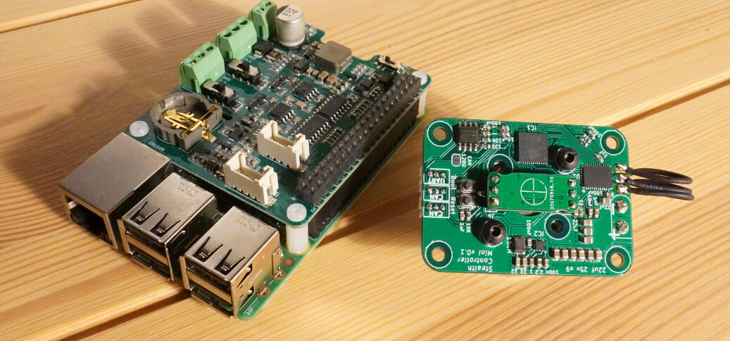
I shrunk down my DRV8316 controller.
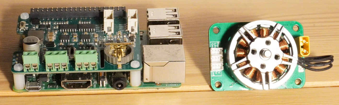
This 36mmx50mm board is designed for 28xx sized motors.
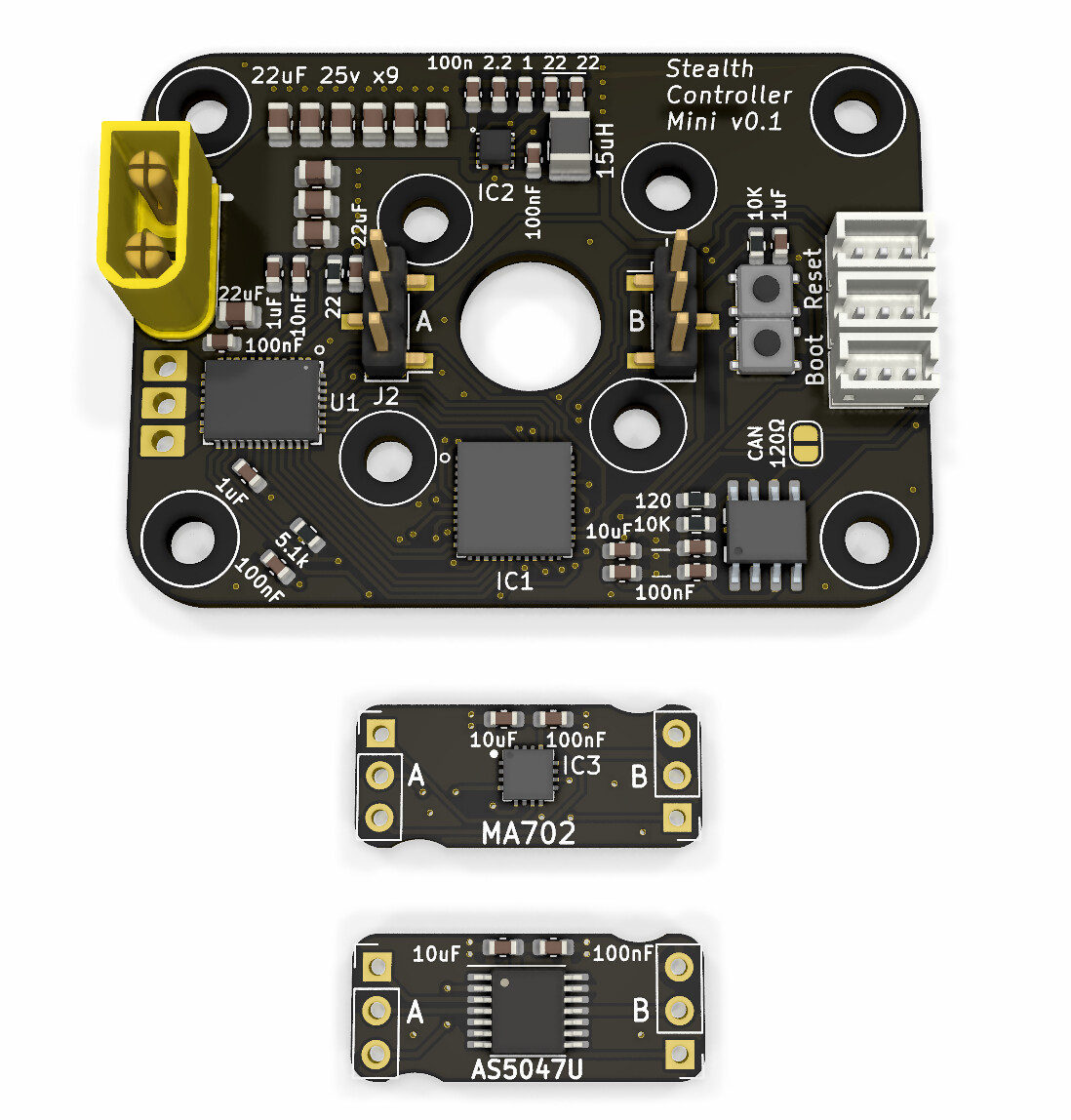
My idea was having pin headers to attach a “daughter board” on the back that could have different sensor modules (say if you can’t find any stock of the original one anymore).
The schematic otherwise is exactly the same as the larger sized board.
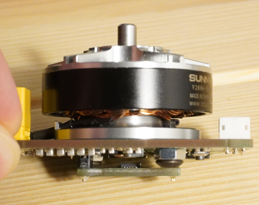
I’ve assembled the first board, (RPi for scale - also the motor is a 2806).
It’s a 2 layer PCB with 2oz copper.
The board looks very nice. Also very interesting and good solution to use a standard sensor plug-in board.
Actually if using SPI you could solder any AS5x4yZ chip which has this footprint and supports SPI.
Are you using the sensor db pin headers as spacers? How do you make sure the motor has the exact axis to magnet to sensor distance required? Some motors may have different geometry.
Are you also using the board as a structural support for the motor? In this case you may want to fabricate the board as thick as possible, or at least use another extra stiff insert in between. The vibrations will eventually crack the solder and components. Modern solder is brittle, and the way the motor is directly sitting on the board it will overheat then cool down from the motor and the vibration stress will eventually crack it. Especially the MCU and driver looks QFN, no legs to flex. So the board will intermittently stop working then start and stop again from the vibrations any time the leads touch or disconnect at the cracks when the motor flexes the board.
The motor sitting on the board will overheat the MCU and driver. This is an out-runner and the stator will transfer heat straight into the aluminium base and into the board and driver and MCU. I would put some hard rubber screw shims or washers between the motor base and board to air-gap it to prevent direct heat transfer, may be even use nylon bolts to deaden the vibrations and limit heat or at least stainless steel or titanium (very low heat transfer and non-magnetic) bolts and screws to limit the heat transfer. Which will raise the motor and you need to re-gap the sensor.
I am curious what the end design will look. Very interesting.
Edit:
These are QFN, no pins to solder by hand. Unless you reflow the entire board in a time-controlled oven.
Yes - the headers are soldered to the controller board first, then the module is soldered at the correct spacing, and pins cut off. So in my photos - I can add more spacing, but cannot reduce it - as it is fully against the headers.
Yes - I didn’t really think about vibrations.
Potential design changes:
I want to get rid of the headers for mounting the sensor module - as it adds too much time to assembly. Maybe I could remove the headers and use castellated edges. It would be worse for handling vibration, but would still retain the benefit of swappable sensors.
Vibration / heat: I could add another PCB between the motor and controller board to act as a stiffener & spacer (it could have cutouts for the connectors). I think increasing the controller board thickness with 2oz copper would be too costly.
Hi Jason really cool controller!
I searched the internet for a miniature controller and found nothing suitable except for your design.
Can you share the project files?
I really want to try to make a board based on your design for my project in a smaller size.
I’m trying to have the magnet under the board. This is not mentioned in the datasheet as a valid mounting option, but I’ve done some quick testing with another board and it seems to work fine. Magnet on top would work too, but you may want to move the pushbuttons.
The MA702 looks to be out of stock everywhere, but the MA780 with similar specs is in stock. I’ve added solder jumpers to allow configuration for the MA780 - but I have not tested one yet. There should also be enough room for an AMS sensor if you remove the MA7xx footprint and solder jumpers.
There are 3 PCBs - The Motor mounts to the 1st, the 2nd is a spacer for the bolt heads and magnet, the 3rd is the driver board.
There would be no bolts holding the 3 board “sandwich” together - except for the outer mounting holes, so I’ve added some slots on the sides for a 3d printed clip - to hold it together during mounting.
Added both horizontal and vertical XT30 connector mounting options - with a breakaway tab.
The SMD section of the board is less than 30mmx30mm. Which is the size of a MHP30. So I might try reflowing with this
@Jason_Kirsons i don’t think it matters but I noticed the middle motor trace from the chip to the solder pad seems to have a smaller cross sectional area.
Edit: and I think some NC pins of the ic’s don’t have a solder pad. But I’m not shure. I would still put the pad for mechanical reasons.
Interesting. Out of curiosity, what is the miniature controller size and amps and frequency and MCU you had in mind? I mean how miniature is miniature?
Wonderful job Johnson.
Thank you very much for sharing the project, I will soon start tracing the driver while I understand kicad.
Valentine
I don’t know which MCU I need yet, I have no experience in setting up FOC.
To understand, I need to drive a 2207 size motor at peak with a current of no more than 3A and <800RPM, the stable current will most likely be in the range of 250-300mAh, The motor will be a rotating cycloidal miniature gearbox, the gear ratio between the motor and the output shaft is 30: 1
The position of the output shaft needs to be known, possibly another encoder. The deviation limit is 120 degrees and 180 degrees per second
Those. this is a servo drive, only with FOC
the motor controller board itself must be 30X30, no connectors, only solder pins, and it must be separate from the motor.
This is necessary because I have the aerodynamic requirements of my VTOL project
Two encoders are external. One on the motor shaft, the other on the gearbox output shaft.
Interesting. You need to sacrifice a lot to get down to 3x3cm, give up overvoltage/overcurrent/short/reverse protection, do a double-sided smt, and use ceramic capacitors instead of electrolytic. Also use at least 4-layer pcb. Just the mounting holes will take up 20% of the space. The smallest force-air-cooled board I’ve seen is the STM’s B-G431B-ESC1 demo board with all these features but that may not work for you.
For that size, imagine you would make a three or more stage cycloidal gearbox, right?
I have one designed for 3D printing with 1:12 and the diameter is 60mm.
Cycloidal will work only as a prototype, and even then just barely. I remember there was a guy, he spent about $3000 trying to make the cycloidal into a semi-production and failed. The tolerances were absolutely unforgiving for you to get all lobes to touch simultaneously. I myself modeled a cyclo on solidworks and 3d printed from engineering polymer with less than 50microns tolerance and failed, too. I even designed an entire parametrized script where you only put the tolerances and cyclo diameter and it produces all the hypocycloid curves directly in solidworks and I only had to 3d print the result, because you are severely constrained by the standardized size of ball bearings that could be produced.
May be you will have a better luck, who knows.
Edit: If you really want something that is guaranteed to work, please check out the design for Split Ring Compound Planet Epicyclic Gear. It’s a strange mechanical idea somewhere between a cyclo, planetary and strain-wave (harmonic) reducer, and also very practical and also allows for tolerances.
They work well if you design them correctly w/ tolerancing and preload… even using a polymer for the gears w/o rolling elements. They’re not as efficient as some other approaches. The one i built had a 60:1 reduction, 20Nm cont/60 peak, with around 75-80% efficiency. But yea they’re not the cheapest solution for hobbyists, or the most efficient. but they’re good for impacts/robust