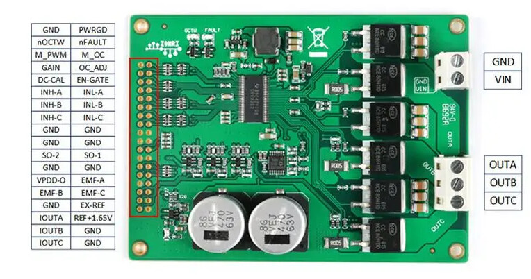
I’ve bought a DRV8302 board from AliExpress which I’ve got working in voltage mode. I want to try current mode and started looking into this. The picture is a bit confusing since this board seems to be implementing the shunt amplification twice:
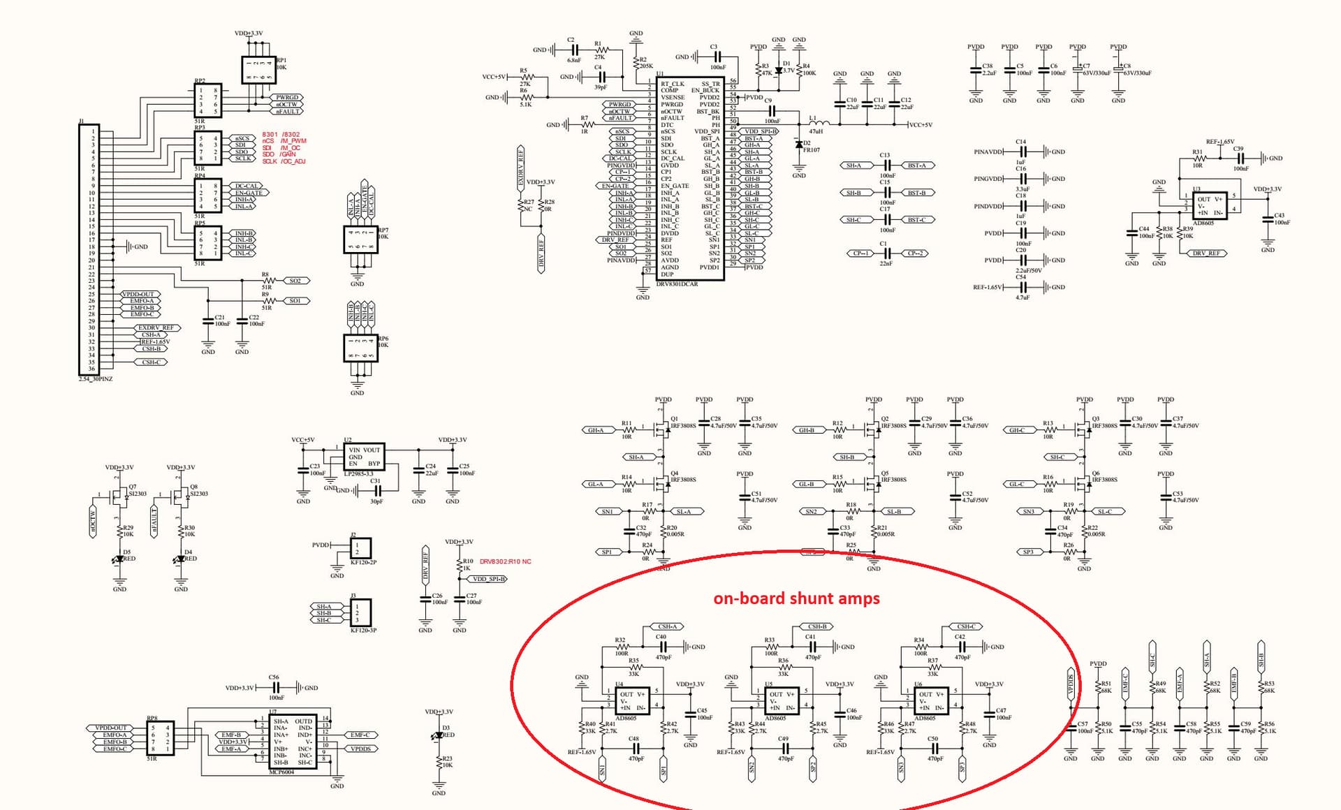
3 Shunt resistors (5mOhm) are placed in the low-side path (between the low-side MOSFET and Ground)
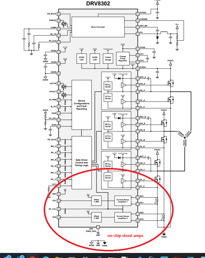
-Shunt voltage Amplification takes place inside the DRV8301’s built-in dual-shunt-amp (Two possible gain ranges -10, 40(50mv/A or 400mv/A) programmable via a PIO on the chip. Only two phases are amplfied.
-Shunt voltage Amplifications ALSO takes place via on-board inverting op-amps, with fixed gain of 12 (60mv/A). This is 3 channel amp.
Both shunt amps rout amplified signal to the board header, where either may be used…
Does anyone know why the board designers saw it necissary to implemet the external (to the DRV8302 chip) shunt amps? Any thoughts on which works better?
Hey! I’ve used the DRV8302 board a few times in different projects. I always used the outputs from the discrete shunt amplifiers. I think the DRV8302 board pins are labeled Ia, Ib, and Ic. It’s worked very well for me with current sensing for torque control.
Header pins SO-1 and SO-2 are from the on-chip shunt amplifier. The DRV8302 has 2 built-in shunt amplifiers with programmable gain.
Header pins IOUA, IOUTB, and IOUTC from the on-board (3 channel) shunt amp (Both the on-chip and on-board shunt amps share the 5mohm resostors)
BEMF isignal s also available on BEMFA, BEMFB, and BEMFC header pins
I’ve confirmed from schematic and some preliminary testing that this is indeed the case. There are some differences on how the outputs look(the on-board shunt amps look cleaner and more “square”), likely the way that filtering is done is a bit different (I’ll post some scope traces later today).
Yes, agreed these outputs look alot better on the scope so I chose to use them (maybe the built-in shunt amps are flawed?). They seem to work welll in current-sense mode, thought I’m still tweaking the PID tuning.
When you go to to tune the q and d current loops, I’d suggest starting with gains: p=1, I=100 for both. Thats been a good starting point for me on a variety of motors small and large
Question: Is there any performance hit doing low-side sensing with 2 shunts vs. 3?
I wanted to use all 3 shunt outputs but my first attempt at that failed (likely a pin mapping issue on my NUCLEO64) but 2 seems to work so I just went with that.
Not really. If anything it might improve performance in terms of speed.
But in terms of accuracy, there are situations where 2 shunts aren’t enough to recover the currents, e.g. having only 2 shunts means you should keep the voltage limit below the PSU voltage to ensure the duty cycle never reaches 100%…