I have two bot wheels similar to the one in this link: BotWheels - Hub motor wheels with encoders — ODrive
Alongside, I have B-G431B-ESC1 ESC from STM. The wheels has both two wires for encoder output and three wires for hall sensors. The objective is to finally connect this to ROS, but for now, I just want to control this wheel by controlling the velocity.
This is the first time I am working with SimpleFOC as well as this board. My experience is always been with brushed motors and brushed motor controllers and this is very new. Tried following the guide : https://community.simplefoc.com/t/b-g431b-esc1-beginner-guide-i2c-guide/515 but not sure if this board can be connected and programmed.
Any insights, or a simple way to start somewhere would be helpful.
Looks like those motors have an incremental encoder, so yeah, they should work fine with the bg431esc. Just hook it up to the encoder pads via the manual from ST, and configure the sFOC encoder class to use those pads, there’s also the hardware encoder class which is much higher performance, but due to a bug in the Arduino definition for the bg431esc requires modifying some of the framework code a little.
Yeah you can do it with this board. I would use the hall sensors, and then use the encoder for higher level monitoring. You can connect hall sensors to this board but it’s pretty hard to get in there and solder them.
Should be reasonably straight forward undertaking but it still takes significant time. But you’ll learn a lot.
The latest arduino has some kind of debugging support, that’s really important in this kind of thing.
I would not use the encoder for motor commutation, that could get more complicated quickly. The hall sensors tell you what you want to know for commutation.
Thank you @Copper280z. Is there a straightforward tutorial which shows Arduino or platformio coding. I am using esp32 as the main control board.
Thank you @Anthony_Douglas. Yes, would take that route of using hall sensors first and then use encoders if that’s the better approach. Soldering is not difficult as i am a hardware guy and have already soldered wires as per the user manual of the board. Its the software i am weak at and struggling.
I finally connected the bot wheel to B-G431B-ESC1 and using Arduino IDE, was able to see the motor rotate in open loop mode. Considering it a success, I connected the Hall sensors and after that nothing is happening.
Below is the code I am using as per one of the suggestion in the forum. However, when I rotate the motor, nothing happens. It just shows -0.07 and 0.00. Is something wrong?
Pole Pairs are 15. I have connected only the Hall Sensors and encoders are not connected yet. This is a brush-less hub motor and I assume only Hall sensors are enough as per suggestion from previous post.
Also, its weird that when I connect multimeter to 5v and Ground pins on the ESC, I was expecting 5v there, but it does not show any voltage. Should I connect external voltage, or any jumper to be connected?
Any help is greatly appreciated.
#include <SimpleFOC.h>
#include <SimpleFOCDrivers.h>
#include "encoders/stm32hwencoder/STM32HWEncoder.h"

// Hall sensor instance
// HallSensor(int hallA, int hallB , int hallC , int pp)
//  - hallA, hallB, hallC    - HallSensor A, B and C pins
//  - pp                     - pole pairs

BLDCDriver6PWM driver = BLDCDriver6PWM(A_PHASE_UH, A_PHASE_UL, A_PHASE_VH, A_PHASE_VL, A_PHASE_WH, A_PHASE_WL);
BLDCMotor motor(15);

HallSensor sensor(PB6, PB7, PB8, 15);

// Interrupt routine initialization
// channel A and B callbacks
void doA(){sensor.handleA();}
void doB(){sensor.handleB();}
void doC(){sensor.handleC();}

void setup() {
  // monitoring port
  Serial.begin(115200);
  // check if you need internal pullups
  sensor.pullup = Pullup::USE_EXTERN;
    // initialize sensor hardware
  sensor.init();
  // hardware interrupt enable
  sensor.enableInterrupts(doA, doB, doC);
  Serial.println("Sensor ready");
  _delay(1000);
}

void loop() {
  // IMPORTANT - call as frequently as possible
  // update the sensor values
  sensor.update();
  // display the angle and the angular velocity to the terminal
  Serial.print(sensor.getAngle());
  Serial.print("\t");
  Serial.println(sensor.getVelocity());
}
@runger, The board is connected to 12v battery. Looking at the schematic of B-G431B-ESC1, it seems like Hall pins get 5v from the regulator on board. Is my understanding wrong and I need an external power source for Hall sensors?
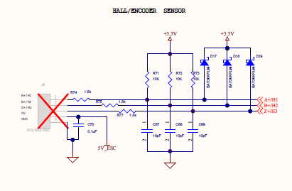
Have you added external pull up resistors? i.e. a 1k resistor between each of H1/H2/H3 and 5V?
If you are missing physical external pullups then you could change code to:
sensor.pullup = Pullup::USE_INTERN;
This is a botch approach because I think it’ll make the above code work but when you add a noisy motor it’ll break again as the internal pullups are too weak (about 20Kohms).
No. I have used internal pull-up in the code. Is that necessary? The question of 5v on sensor pins still remain. Just wondering if there is a flag, or a bit to be set to get 5v from the pin?
BTW, thanks for all the videos @Owen_Williams. Reached here following most of your replies and videos.
From memory (3 years ago) I had a seriously complicated pullup setup. i.e. a pullup and a voltage divider.
On my halls (part of hoverboard motor), the hall needs 5V but the esc1 is a 3.3v and not 5V tolerant. therefore used a 1k pullup between h1 and 5v, h2 and 5v, h3 and 5v and then a voltage divider to step down 5v to 3.3v for each H1, H2, H3. So needed about 9 resistors. LOL
Did you add external 5v to the Hall sensors? If yes, then I need to recheck the connections.I also have a Flipsky FSESC from one of my previous projects. Looking at some of your videos, I am also thinking of jumping to it. But wanted to know why its not working, or if it does not work at all.
You can definitely use the 5V from the board (pins are next to the hall sensor inputs) and the ESC1 has provisions to accept 5V signal levels on the hall input pins built in.
Are there 5V when powered from USB? if yes, then you probably burnt the onboard buck converter. I have a few of such boards, you can still use the MCU and CAN bus on them at least…
Oh yes. When I connect from USB, it shows 5v. Maybe I would have burnt the Buck converter. Even then, Can I use external 5v and use the board?
Secondly, are the hall sensor pins 5v compatible since they seem to be designed to use together and board already provides 5v?