Thank you for feedback
Yes i am confused about this i will reverify this again in all the three gate drivers.
Could you please suggest what are the other data / waveform i can share to get more clarity.
I am trying they have over modulation feature which i have enabled and i could get additional 200 rpm but still less by 300 RPM, for maximum speed their recommendation is go as high as possible value of modulation index (100%) but currently even if i go beyond 85% i do not see any increase in speed.
I just wanted to clarify one point if i add external boot strap diode between Vb and Vcc will it help as there is 25Ohm resistor internal to the driver.
Thank you for replying. Yes i plan to buy the competitor product and capture the waveforms, but my worry is i can only verify the U,V,W phase currents and differential voltages.
Without even knowing if you’re driving it sensorless 6 step BLDC or any other mode of control MCSDK offers no one can begin to try and help.
Motor full specs including feedback device if any and if used would be bare minimum.
full SDK project and someone knowlegable and willing to help would be another cruical componnent.
I suggest you register on here: STM32 MCUs Motor control - STMicroelectronics Community
and ask the same question with waveforms and full schematics. Better chance getting help related to ST SDK on their community than SimpleFOC ;).
or get simpleFOC compiled for your MCU and ask the question again here 
1 Like
Oh, I was under the impression you had personally tested it. In that case, I think it’s just voltage confusion. Sasquatch was likely correct in post 7 that the motor is rated for 48V RMS (which can be produced with a 60V supply and SVPWM), and the competitor product’s 52V is also RMS. Presumably the test would be done under load, hence being toward the low end of the rated speed range despite being a bit higher voltage. If 52V was their supply voltage, then they shouldn’t be able to reach 3300RPM even unloaded.
So I stick by my original advice: Want more speed, use more volts 
I have personally tested at customer place who are using those controllers, now I want to buy on my own and compare the waveforms.
I have performed tests on the competitor and observed the following differences with 48V Power supply
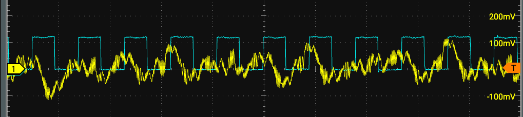
Competitor waveforms
Phase currents-1
DC Current
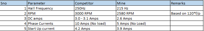
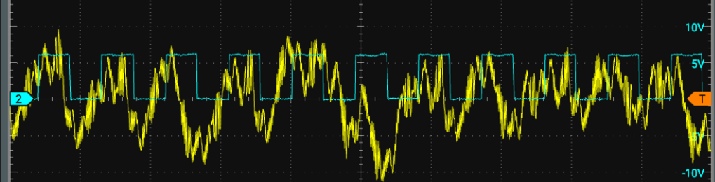
My waveforms
DC Current

I am using FOC, Hall sensor based. Based on your experience if you can provide some suggestions i will look into.
Cyan square wave is gate voltage? It looks like highside on yours and lowside on the competitor, since the phase relative to the yellow current wave is opposite. Although I’m surprised any current is flowing at all when it looks like 50% duty, which is zero in the AC output voltage space (higher or lower than 50% gives relatively positive and negative output voltage). But maybe it’s slightly off 50% and that’s all it takes with no load due to the low resistance of your motor and high DC voltage.
What modulation scheme are you using? Try Trapezoid120, or running the hall sensor angle through SmoothingSensor with SpaceVectorPWM. Looking closely at the SVPWM waveform, I think trapezoid will give you 15% higher effective voltage when moving in hall sensor steps. As I understand it, the ideal is to drive a motor with the same waveform that it produces when run as a generator, which depends on some details of the construction and winding. So if your motor produces a sinusoidal back EMF, then smoothed SVPWM is better, whereas if it’s more trapezoidal then Trapezoid120 will be better.
Cyan is the hall signal waveform. I am using SVPWM. When run as generator it is producing the sinusoidal back emf.
There are problems with VGS waveforms that may solve the issue. Thank you for support.