Does Gate Resistance improve RPM

I have a very generic question does gate resistance improve the RPM of a motor, i am falling short of around 300 rpm. The boot capacitor change has improved the RPM by 200 (from 1uF to 4.7uF) but still short of 300. At present the gate resistance is 22Ohm for each Mosfet (2 mosfets for upper side and 2 mosfets for lower side), i plan to change to 15 ohm each, the idea is it will improve the rise and fall times. The competitor product achieves around 3300 RPM at 52V and i get around 2700 they are fine even if i get 3K. I am sorry that i am asking without sharing any of the hardware and software details, but from your experience if you can point out something, it will be helpful.

One other dumb question, i see in this forum people measuring the propagation delay, dead time, rise time etc, i have never done these measurements, how critical are they, i am only verifying if the motor is running or not and the phase currents are sinusoidal or not. :slightly_smiling_face:

Just to add few details of the motor

image

Few questions i have is 48V is the rated voltage of the motor, but if you apply FOC you can only get Sqrt(3)/2 = 0.866*48V = 41.5V, there is over modulation which i applied i am not sure how much voltage will be applied to the motor. Is there any method i can know the voltage i am applying to the motor using oscilloscope? I have been trying to get the answer for measuring the bus voltage but i am not able to find an answer.

What is the electrical RPM and your main loop update frequency? My guess is the applied voltage angle is lagging slightly behind the ideal. I once tried adding compensation for that by measuring the time between sensor sampling and the call to setPwm and extrapolating the position from velocity. It worked, but caused buzzing at zero speed due to random noise.

For a quick test, try field weakening to see how high speed you can achieve, and whether loop rate or torque falloff becomes the limiting factor. I made a simple wrapper class that adds some phase advance proportional to the applied voltage Arduino-FOC-drivers/src/encoders/FieldWeakening at dev ¡ dekutree64/Arduino-FOC-drivers ¡ GitHub

As for your question about voltage, usually the limiting factor is when the rotor explodes from centrifugal force (assuming it’s well balanced so it doesn’t impact the stator first), and motor voltage ratings are usually a small fraction of that. They’re more of a ballpark value to get optimum efficiency, so whether they mean 48V power supply or some interpretation of 48V in the 3-phase coordinate system, I wouldn’t worry if you need to go higher to get the speed you want.

1 Like

Thank you for reply, it is 5 pole pair motor and the electrical RPM from 120*f/p it is 250Hz. The switching frequency is 15KHz. I will try field weakening but the main concern is if it can provide the necessary torque, but i will give it a try.

I tried flux weakening, i got 100 RPM additional but in between there are some phase current spikes so i am not sure if i can go with flux weakening.

Driving mosfets too aggresively will kill them by exceeding gate current limit or du/dt limit. Saying that estimated 40-50A 80V mosfets are specced for 2-5 ohm minimum so 15 ohms should be safe
Without knowing what gate driver you’re using its impossible to say what hampers your performance but mention of 2 mosfets per phase and boot capacitor suggests weak drive loaded by 2 gates charge = long turn on time.
with strong driver and 20nC gate charge(typical modern 60A80V mosfet) you’re looking at 120ns switching, with 300ns dead time to be on the safe side.
if you used something ancient like 2xirf540 per leg, swithing time will be around 400ns and dead time should be 1us without measuring it….still only 1.5% of pwm period, it shouldn’t matter that much if your gate driver can deliver 0.5A at 10-15V.

1KW at 48V requires only 25/50A continious/pulse currents surely you could find single mosfet that’s up for the job?

1 Like

Thank you for the reply i will study the things you have told him it may take some time for me to understand. Sorry that i have not shared the details clearly.

The MOSFET driver is 2ED2182S06F and the circuit as below

Fig1

The MOSFET IC is IRFB4110PBF and the circuit is as below

Some of the calculations i found out from the net are

Total gate charge = 150nC, 2 Mosfets = 2*150nC = 300nC

Boot strap capacitor for 0.1V ripple = 10* 300nC = 3000nF = 3uF and hence i updated the bootstrap capacitor value 4.7uF, C15 i updated with 4.7uF.

Another thing i found out is the bypass capacitor shall be 10 times the boot strap capacitor value = 4.7uF = 47uF, C17 shall be 47uF but at present the package is not supporting on the PCB so i kept 4.7uF.

I planned to remove the C11 capacitor as per the data sheet diagram,

there is no capacitor between 12V and ground. Is it correct? I have not yet removed i am confused to retain or remove.

The gate resistor is 22Ohm i don’t know the calculations how to select gate resistor. Yes i plan to remove one mosfet, but i am confused whether to first make it work with 2 mosfets and then go to single mosfet?

Current state of testing is the system is unstable with intermittent high phase current pulses with shoot through kind of scenario.

Please review the design and help me to rectify the issues. Thank you in advance.

I could get the answer for the above clarification. The 12V is derived from the battery power supply and there a by pass capacitor is used with 470uF. So, i think not required to use a big capacitance value for C17, at present i have mounted 4.7uF which i will change to 470nF to avoid spikes near the driver IC. Is my understanding correct?

Leave c11 as is or bump to 1nF, it’s there for high frequency filtering. Reservoir capacitor on driver supply should be as close to the chip as possible or trace impedance starts playing a role.

Looking at your motor specs again I think the ratings supposed to be 48V 3ph AC RMS and 60V DC driver supply… and here is why:

With driver 200ns propagation, plus gate voltage rise time of 300ns and transistor turn on/off delay time of 25/75ns you should aim for 600+na dead time(unless scoped and tuned) that’s still no more than 1.5% of torque loss. Even loaded you should be reaching full speed without a problem

If switching+dad times were too long you would still reach max speed unloaded and only under full load that would begin to be a problem.

Thank you for the reply, the DC driver supply i am using is 48V, any comment on the Gate Resistor of 22 Ohm is it ok? After changing the boot strap capacitor to 4.7uF i have not changed the gate resistor.

resitor won’t change much, it should be safe to go down to 2-4 ohms, but other than increased emf interference it won’t change much. i believe your motor ratings are given in RMS AC voltage/driver DC supply voltage, although 48VAC is approx 68V peak, so it should be 48/70 V.

I would leave driver circuit as is and try increasing voltage to 60V short time unloaded it won’t hurt.

BTW outside of hobby rc bldc motors rating are given in RMS VAC voltage and current.

Thank you very much for your time and reply, i have done few changes in my hardware

  1. There were 2 Mosfets each on high side and low side, now i made one each on high side and low side, to reduce the load on the driver and verify for any speed improvement. I have not found out any change in speed.

  2. But as a second test today i measured the low side PWM after the driver and between the gate and source of the Mosfet and found the PWM has significant rise and fall time as below around 11uS for rise and 10uS for fall time, Total is 21uS and i am running PWM at 15KHz it is 66uS and i am loosing almost 31% of the period. So, i feel the Gate resistance has influence on rise and fall time, so i am planning to slowly reduce in steps of 15,10 Ohm etc. Please provide your comments on the waveform if i am missing anything.

    I am not expert but trying my best to understand and rectify the issues.

i believe your motor ratings are given in RMS AC voltage/driver DC supply voltage, although 48VAC is approx 68V peak, so it should be 48/70 V.

I would leave driver circuit as is and try increasing voltage to 60V short time unloaded it won’t hurt.

I verified with the standard controller available in the market and it rotates upto 3300 RPM at 52V.

I’m out and about so can’t post detailed response, but have a close look at your scope screen and try to think why 10us rise fall times are not real.

Added some time later:

A clue is in the red circle :wink:

Bump hat sampling to 10MSa/s, measure again and post that screen again :slight_smile:

1 Like

Yes what you told was correct, the oscilloscope setting is the problem. The updated waveforms do not show any significant rise or fall time issues. It is in nanoseconds, now i don’t know what the root cause for speed issue is.

You say shoot thru? Did you burn some mosfets? I don’t know the best way to address everything, so I hope what I say doesn’t come off condescending or anything. I’m only trying to help.

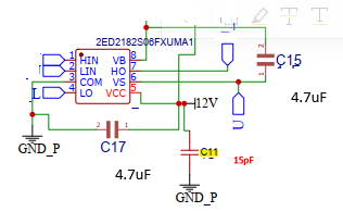
I would make sure that the gate drivers have both bulk capacitance (I think you are calling this C17?) as well as decoupling capacitance. I would imagine this to be a 100nF ceramic capacitor that will react to very fast switching first, then a bulk capacitor like a 4.7 to 22uf capacitor to provide the large current needed to overcome gate capacitance. 1nf is not anywhere near enough, 0.1uF/100n is typically the minimum, 470nF might start stealing enough of the cap’s ESR to defeat the point of having a decoupling capacitor to begin with, going more towards bulk. If you have very sensitive stuff going on, maybe then you also add 10nf in parallel. 1nf is tinytiny, I’ve only seen used for RC circuits. Remember that certain ceramic dielectrics like x5r lose like 50% or more of their rated capacitance when approaching the rated DC voltage, for that bulk cap. Tant or poly with low ESR are the best!

Do you have battery voltage capacitance near the mosfets as well? I do not see any pictured, Essentially a snubber capacitor? I do not believe this is negotiable. Your battery’s impedance is never zero, (always remember this!!!) that plus the switching of inductive loads are going to spike voltages like crazy if there is no fast place to pack that energy! Could that be why you see current spikes?

The battery or source impedance is also why 10X bootstrap bulk capacitance to the gate driver supply is also non-negotiable, BTW!

You need proper capacitance on the boost side of the gate driver, it is imperative that this capacitor does not discharge because that will settle the mosfet in the linear range and it will release the smoke pretty dang quick. I haven’t looked at the code, or your gate driver, but it also needs an undervoltage protection that prevents the upper gate from even trying till this capacitor is charged otherwise the result is the same as using a capacitor that is too small.

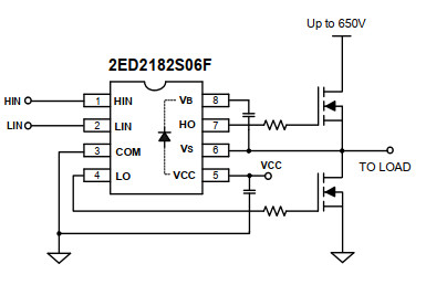
Last, it looks like your gate driver has a built in boot diode and resistance. Sometimes that isn’t going to provide enough current, so it might be necessary to use an external boot diode and series resistor. Internal diode drivers usually give a boot diode resistance, but since you aren’t doing anything crazy I doubt this is your issue.

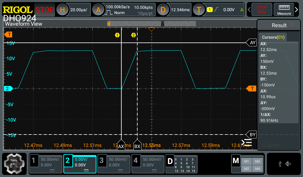
As to gate resistance, I believe you want it as small as possible without introducing harmonics (not sure if that is the right word, maybe ringing?) I think google might explain better than I do here, so I’d search for “tuning h-bridge gate drivers.” and take it from there. The datasheet for a TMC5160 stepper driver has a very good section that explains choosing gate resistors and adding additional components that might let you switch faster without negative repercussions, plus an example (great scope traces!!) It also goes into detail on how there is no set value for this stuff, maybe outside very expensive software to simulate the PCB at the very lowest level. Asking for a globally good gate drive resistor is kinda a half baked question, maybe we can offer one that will switch at 75% of “the best”, but chasing the last bit requires measurement.

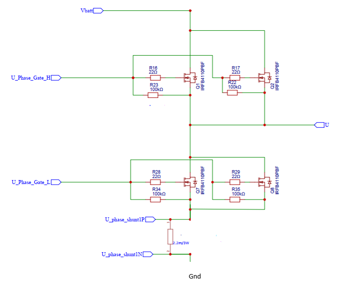
Are R22-R35 intentional? I would remove them. Gate drivers both source and sink current, those serve no purpose unless I am missing something?

Hope that helps!! Happy to hear where I might be mistaken, because I’m still learning too.

1 Like

R22, R35 are there to stop gate from triggering in an unlikely event of DC bus voltage being present before driver is powered up and it’s outputs are out of Hi-z state, if such state exist. No harm at 100k.

Before ringing occure you may exceed gate maximum current of MOSFETs, unlikely on high side as boost capacitor ESR will be the limiting factor. For “low ESR” electrolytic that’s around 1 Ohm for 4.7uF 25V capacitors. Drivers used here are rated for 2.5A, in theory gate resistor below 4 Ohms will exceed that, however briefly(few ns).

Scoping of high side gate voltage would be necessary here to determine if it’s up to the scratch. FOClearner, be sure your scope can accept 60V on inputs, or you use X10 probes, make sure scope is isolated from ground, to pick up gate ringing you would have to crank sampling rate all the way up too. On the screens you provided actual rise time is anywhere between 160 and 240ns.

X5R looses up to 30%, and y5v looses up to 60% of nominal capacity below 5⁰C and above 40⁰C(of the top of my head). X7R is minum suitable here.

I would say the FOCLearner’s circuit is ok. And the problem is either library setup, or CPU speed. With low side sensing requiring “some” extra floating point math I can see that overwhelming the slower MCUs, especially if current is calculated every PWM cycle.

Admittedly I know nearly nothing about SimpleFOC innards.

1 Like

Thank you to both of you for helping and sharing valuable inputs, I will write a detailed mail once i capture the waveforms and post it. Sorry to say at present i am not using the Simple FOC code, which i am migrating very soon, i am about to order hardware boards and getting started at present i am running the STM32 MCSDK generated code. I don’t have enough confidence changing the STM32 software apart from the configuration parameters.

Just to add as of now luckily i have never observed the Mosfet failure, i am running on the power source before i run it on the battery.

Sorry there was a delay in testing due to a component failure, i had to replace it and hence the delay. I have captured the waveforms of Boot strap capacitor and the High side driver waveforms. There does not seem to be abnormality i mean lot of unused duty cycle. The Blue waveform is differential with negative on source and the positive on Vb and Drain of Mosfets. Also captured the PWM input high side before the micro. For differential probe the factor is 20. Any suggestions what i am doing wrong the speed does not seem to increase. The yellow is the phase current. Request to please provide your feedback if any mistake it can help me to acheive my goal.

I don’t really know what to look for in those traces, but maybe you could probe the competitor product and see if you can tell what it’s doing different.

1 Like

I’m not that familiar with rigol GUI, but it looks like Vboot drops by nearly 2/3 that’s quite worrying. unless there is an offset and drop is only ~2V..
This is most likely an measurement error caused by high speed transient of VS(Vboot negative, motor phase) from +48V to approx -1V when high side transistor switches off.

Your hardware looks solid, at least from the extremely limited info you shared.

Read up on tuning STM32 MCSDK control and focus on that, it seems there is a ton of literature out there. from my experience their support is quite good at pointing in right direction too.

1 Like