Hello everyone, I’ve been working on an improved version of my previous version 5 motor driver. The new Powerful Brushless Motor Driver v6 features many improvements, and also moves to a 14 layer PCB which increases the cost by a lot especially for small quantities. I know that similar performance and features can be had for cheaper with other more reasonable designs, but I want to cram the maximum performance into the smallest size while still being user friendly by using connectors for everything.
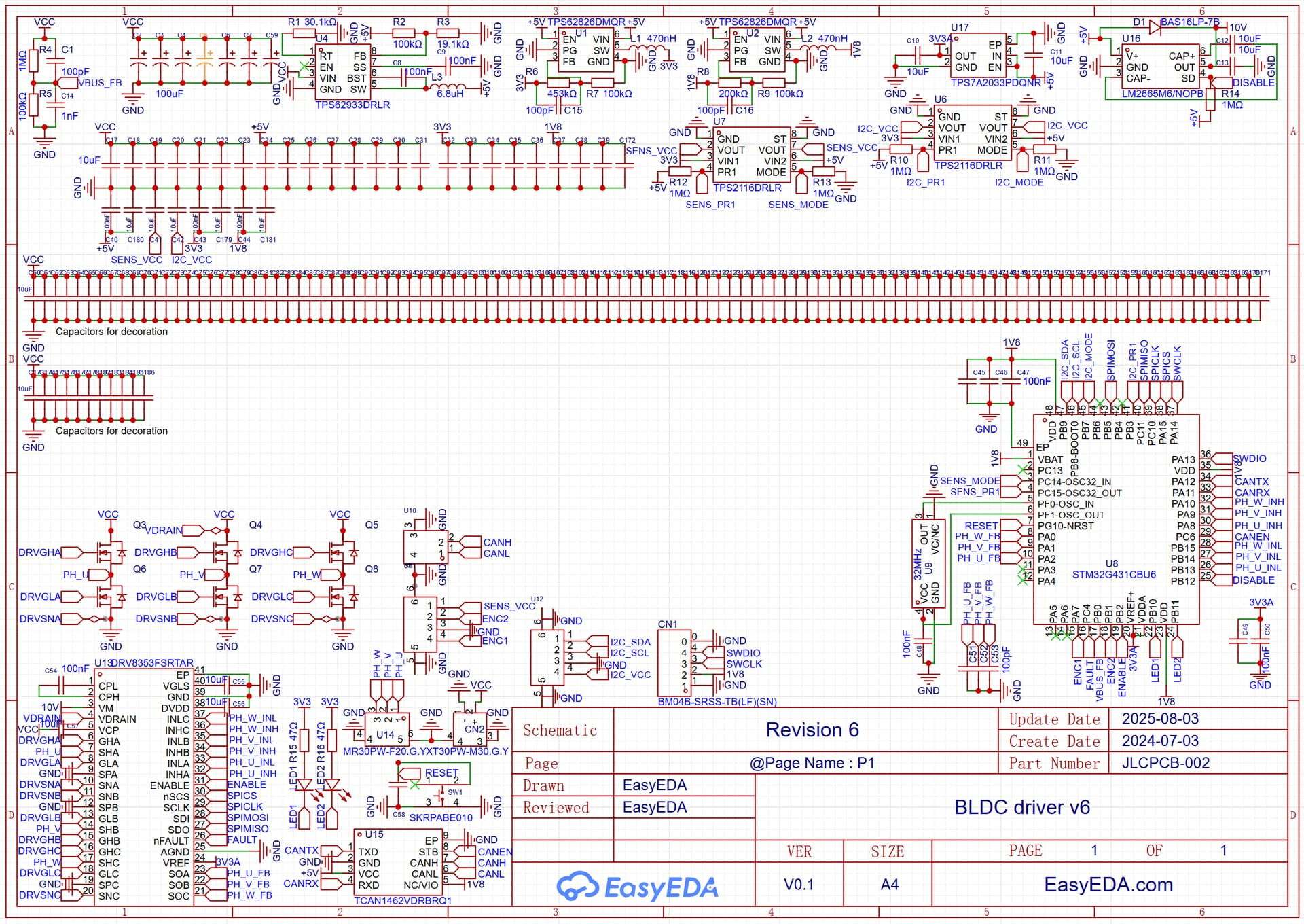
Screenshot of schematic (For a clearer version and PCB click the link above) updated 4 Aug
The new version aims to improve the accuracy of the current sensing (DRV8323 in previous design had offset calibration issues, and there was a small amount of interference when phases switch close to sampling time). Also the performance doesn’t degrade at low input voltages anymore, and the supported input voltage can go as low as 7V. The MOSFETs were also replaced with more modern ones which have a lower resistance (1.2mΩ typ.) and gate charge.
This design emphasizes reducing idle / low-load power consumption, to suit applications where the motor may need to maintain position when stopped, such as parking a car on a hill. This is achieved by powering the STM32 with 1.8V and using the DRV8353 in dual supply mode, with the 10V gate drive voltage being generated by a 5V buck followed by a doubler charge pump. Although I would prefer keeping 3.3V and using a STM32 with integrated buck, these STM32s are very rare and no suitable ones are in stock. RDSon current sensing is kept from the previous design, although with some slight changes when migrating from DRV8323 to DRV8353.
The design adds 2x M2 screw holes for mounting, and now considers the space taken up by the other end of the connectors. The PCB now extends under this area, giving more space for components, leading to a smaller size overall when system integration is considered, and a larger PCB area means better thermals too. I am also going to use JLCPCB new blind slots, which gives more clearance under the power connectors (otherwise they will touch the PCB when inserted).
The tiny MOSFETs on the power outputs in the previous version which had soldering reliability issues were replaced with a power mux IC that can switch between 3.3V and 5V. This also gives higher current output capability, and prevents the MOSFETs from suffering permanent damage if the output is short circuited accidentally.
I also added a TCXO oscillator, which I intend to use for accurately syncing position and velocity across multiple motors.
The motors I plan on using with this driver are the Robomaster M2006 P36 and the Robomaster M3508 P19. I will also use it to drive solenoids and other high power loads, although the hardware cannot drive stepper motors well. I’m also investigating the possibility of adding other compatible motors by either making a custom motor PCB using two linear hall sensors, or attaching a AS5115 magnetic encoder to a motor.
Any feedback on my new design would be greatly appreciated.