
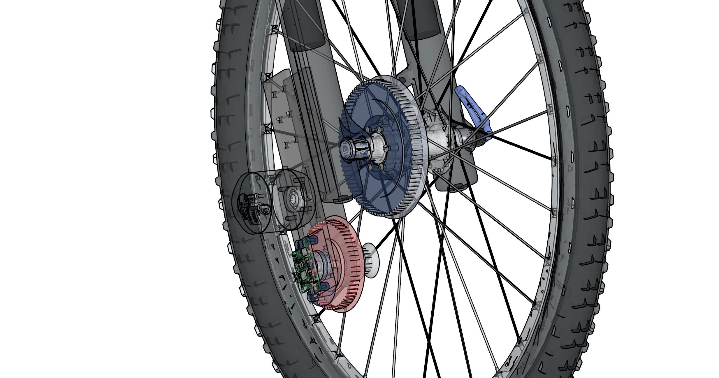
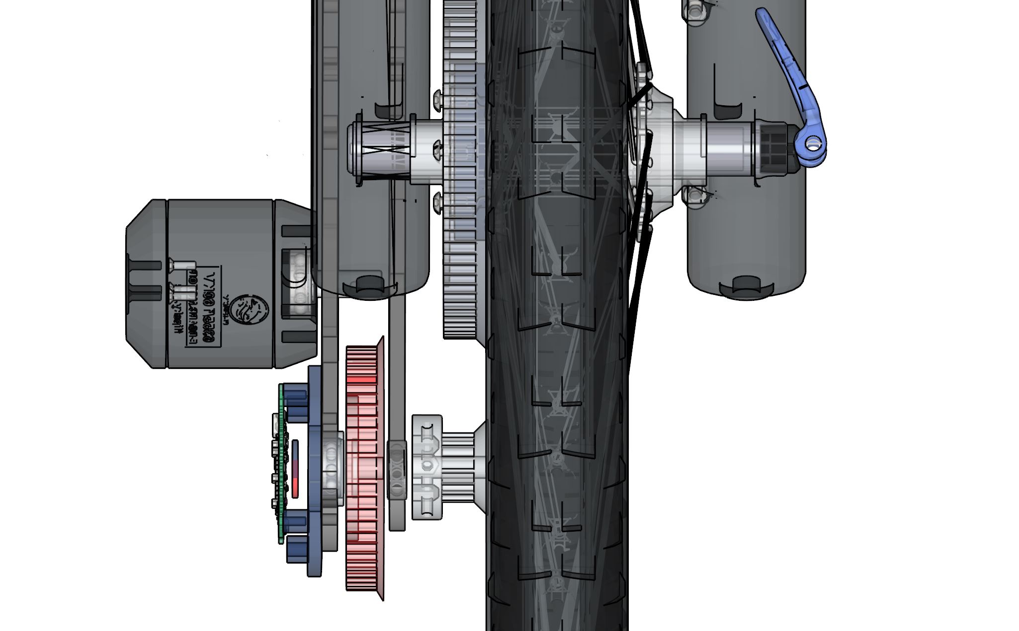
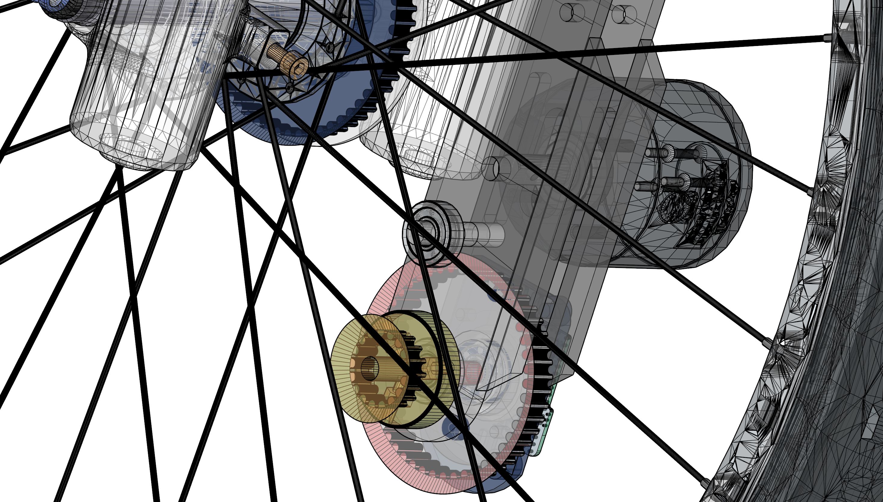
Thus 17 teeth on the secondary pulley and 88 teht on the hub gear (HDT 5 - 12mm belt) gives 88/17=5,1764705882352941176470588235294
So when the wheel turn one rotation the motor turns 25 times ( 5 x 5 ratio).
And since our motor had a (24v * 190kv = 4560rpm @ no load) We can expect a approximate rpm of 4560/25 = 180 (no load).
How many rpm can we expect at body load on a bike?
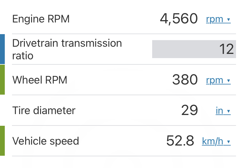
Edid: A gear ratio of 12 is more suitable
Remember the flintstone principle. We help the machine from standstill to movement by peddling. This means we can move the torque curve on the gearing.
This is with a lower gear ratio. 1:3 on primary gear (15 tooth pulley 45 tooth gear) and 1:3,73 on the secundary gear (15 tooth pulley 56 teeth on wheel). Total (3 x 3.73) 1:11,2 gear ratio.
Using a 190kv motor with 24v (4560 rpm) / 11,2 = 407 rpm (no load)
How do you do regen-braking?

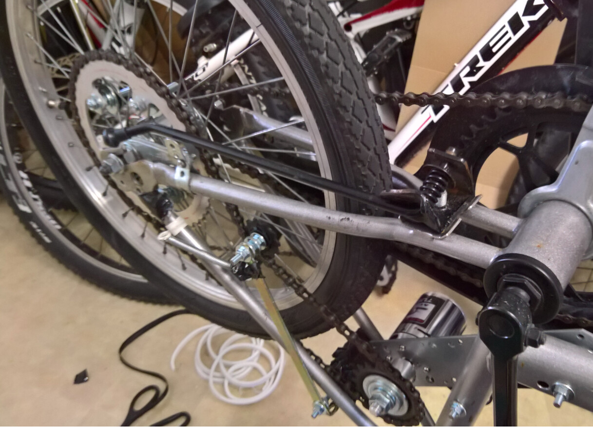
Because you are working on an electric MTB, I wanted to share my old electric bike I made a few years ago when I finished high school. With this bike you can manage the throtlle with a twist throttle system just like a regular motorcycle.
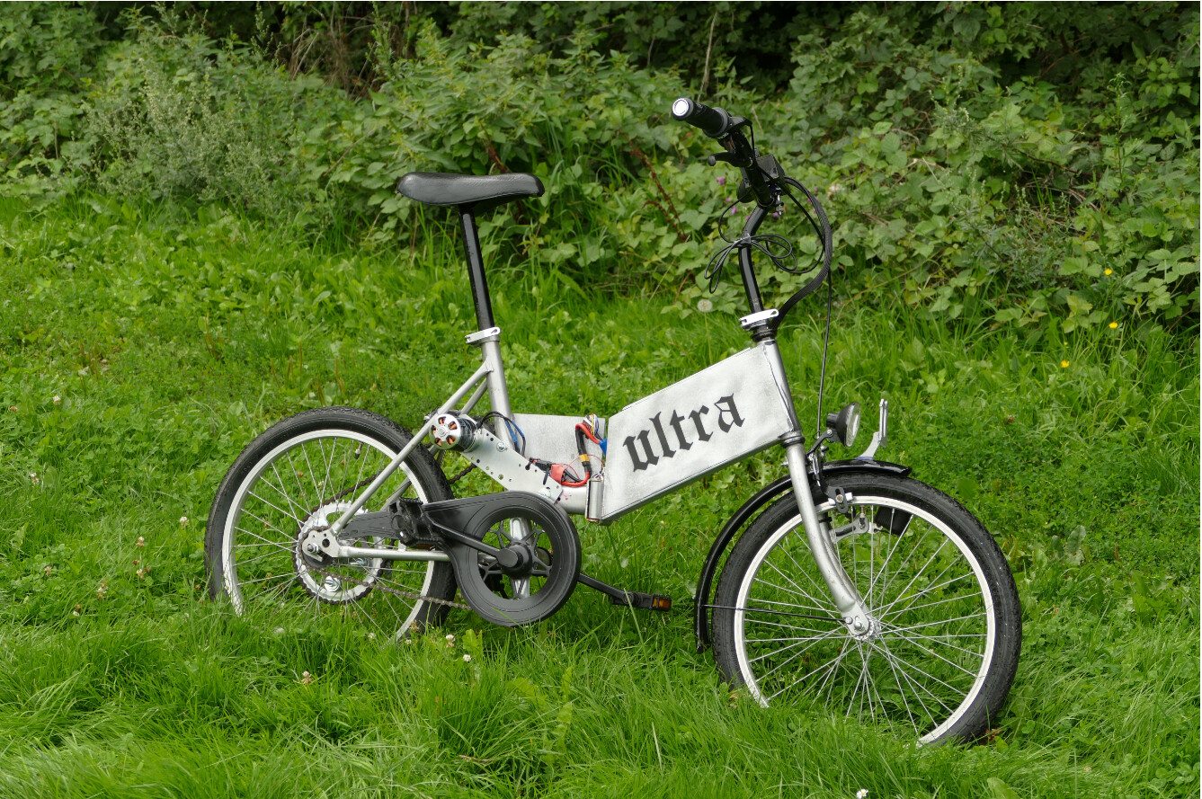
It uses a large hobbyking motor and a regular ESC (I did not even know what FOC was back then). The control is done with an Arduino. A large struggle was mounting a gear to the wheel because I did not have a 3D-printer back then. So it uses many bolts to mount it. It does not seem sturdy but it still holds today!
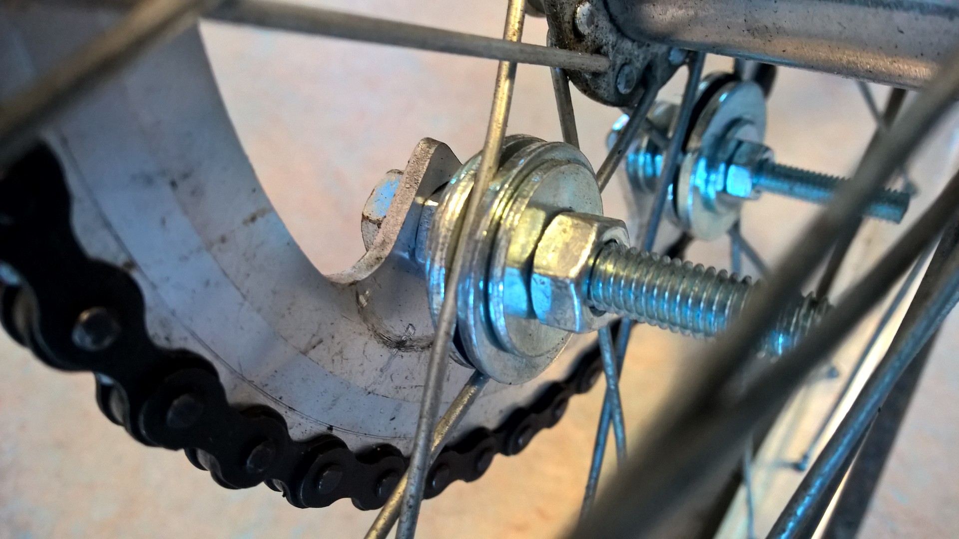
The largest issue with this design is that I could not manage to perfectly allign the gear in the center. So it uses a tensioner with a spring to make sure that the chain will remain on the gears.
Two issues with the bike: Not much torque in the starting position and when starting the motor on higher speed the chain will come off (because the motor does not know the speed). Both issues could be resolved with FOC! I am curious how it goes with your bike! Maybe I will improve my old bike with FOC in the future! 
Two suggestions for your bike:
-
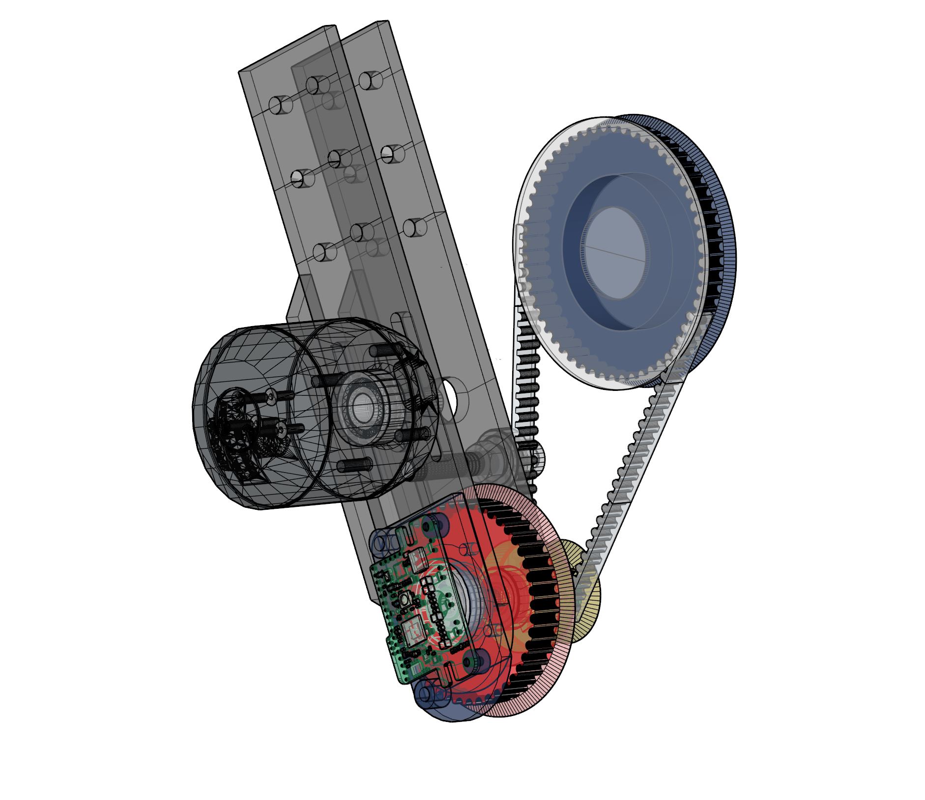
It looks like your encoder is fitted after the gear reduction instead of directly on the shaft of the motor. I would suggest moving it directy over the shaft of the motor.
-
Your gears seem quite small for handling the torque on a bike. Also lots of filth will go into your gears and larger gears handle stuff like that a bit better. You can always try this first but if you have struggles with the gearing system you can always make it bigger!
Awesome project and good luck !
Hej Wittacactus
Nice!
I will try to find room for a tensioner for the secondary belt.
The motor should be sensored. There is IMO no need for the magnetic encoder in a bike scenario if the motor has build in halls.
My plan is to fortify the gears with 2mm or 1mm stainless steel (belt retainer on one side).
Maybe some sort of shield can keep out the worst filth. Obviously a chain is also doable, but would need a gear to be fitted to the disk brake hub,
What is your gear ratio and how did you find the motor to handle climbing hills? Right, its hard to compare with and without FOC.
There is space for a 8mm bore skate bearing as a belt tension device. Depending on the size of the gears and belt length, it might work with just a sealed bearing and belt retainers/ large washers.’
Edid: Maybe a 6mm bore is more suitable. We need space for a lock-nut or tree.
By threading the holes for the belt tensioner, we just need a single lock-nut on a flat head hex bolt. It’s probably wise to use a drop of lock-tight (glue).
The primary belt is 12mm or 15mm and the secondary belt is 9 mm, both HTD 5 mm.
To compare the gear ratio. This scholar uses a 12 tooth pulley and 148 gear with a 160kv motor @50v (gear ratio 1:12,33).
Obviously running the motor @50v using the infamous VESC6 gives lot of torque, but pay attention to how his experience is with FOC mode on vs. off.
The range vs. torque vs. speed vs. price is also a consideration.
In the video he reaches 36 mph (57 km/h), which is more then twice the, by EU law, allowed ebike speed. With a 24v battery and a higher kv motor, I asume we should be able to hit 35 km/h, factoring in the much lower wind resistance, with twice the range.
Here is a calculation based on 160kv @50v (8000 rpm @no lode).

According to this he reaches approximately 60% of the calculated speed. Doing the same calculation for a 190kv motor @24v * 60% is 34 km/h. Keep in mind, that he seemingly does not peddle the bike.

You know that moment, when your first layer is perfect. There is active cooling on the drivers and you just realized that the issue with your extrusion was due to undercurrent.

Anyways… I’m now more or less ready to print nylon gears. Had to do a mayor upgrade on my 3D printer. Still need the G10 Fr4 though.
Does anyone print nylon? How does it print with 1.0 ~ 1.2 mm Ø Nozzles?
If you feel like building a large 40x40 alu extrusion Delta printer
Be my guest : https://grabcad.com/library/beefy-delta-3d-printer-1