Custom hardware (STM32F1 remix on Valentine's mosquito board), when lib_archive=false, getting unable to initialize driver

Hi all,

I’m new to electronics and PCB design, trying to remix the Mosquito board by @Valentine (Thank you Valentine btw for opening your designs :)).

Schematics : EasyEDA(Standard) - A Simple and Powerful Electronic Circuit Design Tool
PCB : EasyEDA(Standard) - A Simple and Powerful Electronic Circuit Design Tool

The board seems to work, tested able to spin open loop, using PlatformIO.

Video : https://youtu.be/srCh_Qw55Qw

Except that it exerts a weird high frequency noise while driving,

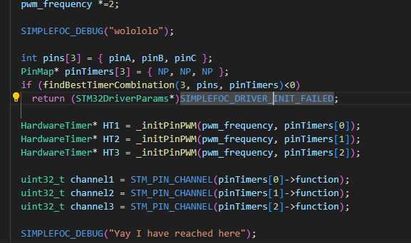
This is likely caused by bad PWM wave forms caused by linking issues ie.not setting lib_archive = false (I’m still not sure of the details, but that seems to be the gist)

After setting lib_archive to false however makes the motor not spin anymore. Looking at Serial debug getting:
00:53:36.546 -> MOT: Init not possible, driver not initialized

Now I’m a little bit stuck. Would anyone be able to illuminate further? (Code also attached below)
Thanks @runger / @VIPQualityPost / @Copper280z’s help already btw!! Really appreciate it.

Code here:


#include <Arduino.h>
#include <SimpleFOC.h>
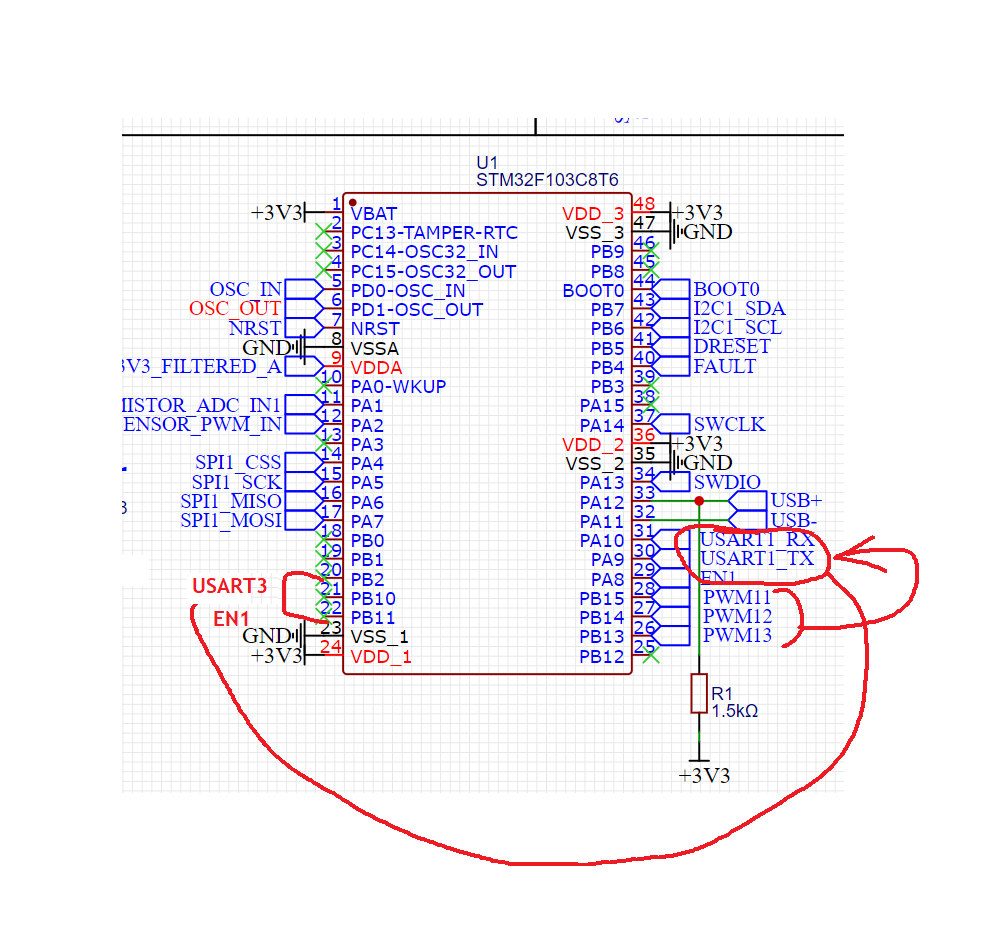
#define serial1_tx_pin PA9
#define serial1_rx_pin PA10
#define PWM1 PB15
#define PWM2 PB14
#define PWM3 PB13
#define DRVENABLE PA8
#define DRVFAULT PB4
#define DRVRESET PB5

// BLDC motor & driver instance
// BLDCMotor motor = BLDCMotor(pole pair number, phase resistance (optional) );
HardwareTimer timer(TIM1);
BLDCMotor motor = BLDCMotor(11);
// BLDCDriver3PWM driver = BLDCDriver3PWM(pwmA, pwmB, pwmC, Enable(optional));
BLDCDriver3PWM driver = BLDCDriver3PWM(PWM1, PWM2, PWM3, DRVENABLE);
HardwareSerial Serial1(serial1_rx_pin, serial1_tx_pin);
const int ledPin = PA4;
int count = 0;
int dir = 1;


void setup() {
  pinMode(ledPin, OUTPUT);

  pinMode(DRVFAULT, INPUT);
  pinMode(DRVRESET,OUTPUT);
  digitalWrite(DRVRESET, HIGH);  
  timer.setPrescaleFactor(1);
  timer.setOverflow(1);
  SimpleFOCDebug::enable(&Serial1);
  Serial1.begin(115200);
  Serial1.println("Motor Ready");
  _delay(500);
  // driver config
  // power supply voltage [V]
  driver.voltage_power_supply = 12;
  driver.pwm_frequency = 28100;
  driver.init();
  motor.linkDriver(&driver);
  motor.motion_downsample = 2;
  motor.phase_resistance = 16.52; // [Ohm]
  motor.current_limit = 0.4;   // [Amps] - if phase resistance defined
  // open loop control config
  motor.controller = MotionControlType::velocity_openloop;
  //motor.initFOC();
  motor.init();  
  _delay(1000);
}
void loop() {
  motor.move(5);
  digitalWrite(ledPin, dir);
 }
1 Like

Hi @Giant_Bee , we were chatting on this topic in discord :slight_smile:

Unfortunately if you switch lib_archive on and then the PWM doesn’t init there is probably something wrong with the pins chosen…

Could you enable debugging output using SimpleFOCDebug and the STM32 debug build flag?

platformio.ini:

build_flags =
    -DSIMPLEFOC_STM32_DEBUG

main.cpp

void setup() {
  Serial.begin(115200);
  delay(3000); // 3s delay to connect your terminal
  while (!Serial);
  SimpleFOCDebug::enable(&Serial);
  ...

It should then provide some information what is going wrong.

— Edit —

Looks like for you Serial is “Serial1”

Hi @runger,

I have done a bit more probing yesterday with Serial debug turned on. And did some println debugging.
I was getting

02:07:42.642 -> Received data: ��OC��� ��3@���������    ��Motor Ready
02:07:42.642 -> MOT: Init not possible, driver not initialized
02:07:42.642 -> 
02:07:46.329 -> Received data: �P�y@����`��Motor Ready
02:07:46.329 -> MOT: Init not possible, driver not initialized
02:07:46.329 -> 
02:07:49.096 -> Received data: {@@��    @���a����aH�������@ ��_���Motor Ready
02:07:49.135 -> MOT: Init not possible, driver not initialized
02:07:49.135 ->

So far I’m finding that “findBestTimerCombination” is failing to find a best score.

image

As a simple bypass I have done:

int pins[3] = { pinA, pinB, pinC };  
  #ifdef HAL_TIM_MODULE_ENABLED
    const PinMap PinMap_TIM_3[] = {
      {PB_15,      TIM1, STM_PIN_DATA_EXT(STM_MODE_AF_PP, GPIO_PULLUP, AFIO_TIM1_DISABLE, 3, 1)},
      {PB_14,      TIM1, STM_PIN_DATA_EXT(STM_MODE_AF_PP, GPIO_PULLUP, AFIO_TIM1_DISABLE, 2, 1)},
      {PB_13,      TIM1, STM_PIN_DATA_EXT(STM_MODE_AF_PP, GPIO_PULLUP, AFIO_TIM1_DISABLE, 1, 1)},
    };
    PinMap* pinTimers[3] = {             
      (PinMap*)&PinMap_TIM_3[0],
      (PinMap*)&PinMap_TIM_3[1],
      (PinMap*)&PinMap_TIM_3[2],
    };
  #else
    PinMap* pinTimers[3] = { NP, NP, NP };
    if (findBestTimerCombination(3, pins, pinTimers)<0)
      return (STM32DriverParams*)SIMPLEFOC_DRIVER_INIT_FAILED;
  #endif
  

Which gets it “through” the complaining, and then no more errors after that. Though the motor still doesn’t turn.

I’m looking into " findBestTimerCombination today to seek more clues, but do you have any suggestions based on these new info?

Thanks and best regards

Hey, if you add the debug code I mentioned and the build flag, it will print the reason it doesn’t find a valid combination…

But I can actually already see the problem: for the STM32F103C8T6 the pins PB13,PB14,PB15 correspond to the negated timer channels CH1N, CH2N and CH3N of TIM1 - we don’t support using the negated channels in 3-PWM mode, they’re only supported as the low side outputs in 6-PWM mode… :frowning:

2 Likes

Awesome, keep up the fire burning.

@runger Interesting. I’m surprised it even worked as is.

@Giant_Bee Yes the pins need to be the non-inverting A8, 9 and 10. Then you need to find alternative UART and enable. B10 and B11 are serial3, go there. B2 will be enable, and Bob’s your uncle.

Usually we strongly advise people to come over here, we will do a free PCB review to make sure you guys don’t waste time and money, a lot easier to catch those on paper before you burn your fingers and hard cash on boards.

One thing, F103 may not have enough processing power to drive SPI, UART, I2C, and USB with all the extra logic I see you are trying to build around, AND drive the motor at the same time. You will need a much more capable one such as G431 or higher, even go for the 7 series. Even better, split out the motor as G071 and use F103 for comms only, as a two-MCU board, and make the two talk using some simple protocol.

Cheers,
Valentine

1 Like

Ops, I missed the build flag part… Sorry just woke up when I replied to you earlier :slight_smile:

I see. That’s interesting. In hindsight I should have done a prototype board first!

Thanks very much. I’ll make adjustments and make a new version.

I’m also wondering as to why it would work as is… Any potential explanations?

One thing, F103 may not have enough processing power to drive SPI, UART, I2C, and USB with all the extra logic I see you are trying to build around, AND drive the motor at the same time. You will need a much more capable one such as G431 or higher, even go for the 7 series. Even better, split out the motor as G071 and use F103 for comms only, as a two-MCU board, and make the two talk using some simple protocol.

Actually I made this board just as a test, so left all the peripherals out. I’m not decided yet but in the end maybe will just have I2C or maybe add CAN for communication, and SPI for sensor, leaving out serial.
I also chose the F103 since it’s more common and I was hoping I can find more support that way.
But in the next version I’ll probably go for what you have used for the mosquito board.

Usually we strongly advise people to come over here, we will do a free PCB review to make sure you guys don’t waste time and money, a lot easier to catch those on paper before you burn your fingers and hard cash on boards.

That’d be awesome! I was a little bit shy, but it seems like a lot of small issues can be diagnosed just on first sight from experience…

Thanks a lot again to both of your help!

If you are triggering the inverse it will work but in a weird way, like hopping on one leg while singing “row row row your boat” backwards.

1 Like

I think it “works” without lib_archive=false because the library uses something like a software PWM in that case.

1 Like

Ok, it’s not exactly software PWM, but without the lib_archive it can’t find our native driver and so just uses Arduino analogWrite(). This is too slow for effective motor control, at least if you value your hearing and sanity.

Nonetheless, the fact that Arduino framework can run PWM on these pins shows it can be done. And if you want to use the batch of boards you have, you could hack the library code to initialize 3-PWM on the negated channels, but using inverted polarity (to reverse the fact that they are “negated” channels). It’s theoretically possible in terms of the hardware, we just don’t support it in the SimpleFOC library.

Why not, you may ask? No reason other than the PWM code is already super-complex, and adding this edge case functionality would make it even more so. Probably we’ll get to it eventually, but unfortunately at the moment its not yet in there.

However, I think you’ll get more value out of replacing the MCU with one that has more flash memory. The STM32G431 MCUs are very attractive in terms of price/performance at the moment, and are only a little larger than the one used on the mosquito.

2 Likes

loL, wor wor wor ruoy taob, yltneg nwod eht teerts, yram yram yram yram, efil’s tub a maerd.

In general I’m expecting this batch to have issues, so revising the next batch may be cleanist. Though I might try your suggestion as well to savage this batch for testing / random small project.

I agree with @Valentine, make your life easier and go for a G4 or F4 MCU with bare minimum 128kb flash, but 256kb would be notably better as I find it’s pretty common to get images in the 110kb range without doing anything too demanding or out of the ordinary.

I think there’s an f40x MCU that’s pin compatible with the f103 that you’ve got on there now, so you might be able to swap the timer pins around and drop the new chip on, with minimal other changes.

3 Likes