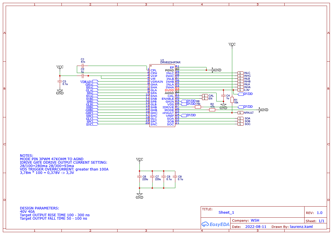
Hi! So for the bldc motor I want to use in my robotic arm (at least in the basepart) I need a very strong bldc controller that can handle 40V and 40A. For the whole project I wanted to use the FOC library as a standard. I didn’t find a good controller that can support my needs so I decided to start building my own. I would appreciate any feedback on the design and any INPUT !
It sounds like a cool project, we can get a discussion going here as the design evolves…
A thought I have: while the NVTFS5C673NL looks like a nice FET, if you actually want to handle 40A, I think you should go for a FET rated somewhat higher, maybe something like this.
The schematic also doesn’t have any bulk capacitance on it yet, but I assume you still plan to add it.
What type of connectors / pads will you use for 40A?
For such high currents the board should be 2Oz or 3Oz outer layer copper, and you may need additional solder or bus-bars on the power traces. It should probably be 4 layers to have a chance to route the signals somewhat away from the power carrying traces, and have decent grounding. The layout will probably be interesting to discuss.
Looks like the driver handles a lot of the complexity for you. It has a fixed 10V gate drive and integrated what looks like a pretty sophisticated charge pump circuit for the high side drive…
Welcome, and thank you, this is interesting. Please share your progress.
On the driver choice, the cost of one driver is over $200 at JLC, This will be a very expensive driver board. Also, the availability is very limited these days with the silicon shortage and all.
On the MOSFETs, as @runger pointed out, you want a lot of headroom to handle 40A. My Level2 electric car charger is 30A, so designing a PCB for handling 40A continuous power per phase is not a trivial task. In addition to that, the nvtfs5c453 are out of stock completely. You need a lot physically bigger mosfet to make good copper contact to carry that much current. I would even go for TO-263-6L or HSOF-8 packages/footprints to ensure sufficient contact and thermal headroom.
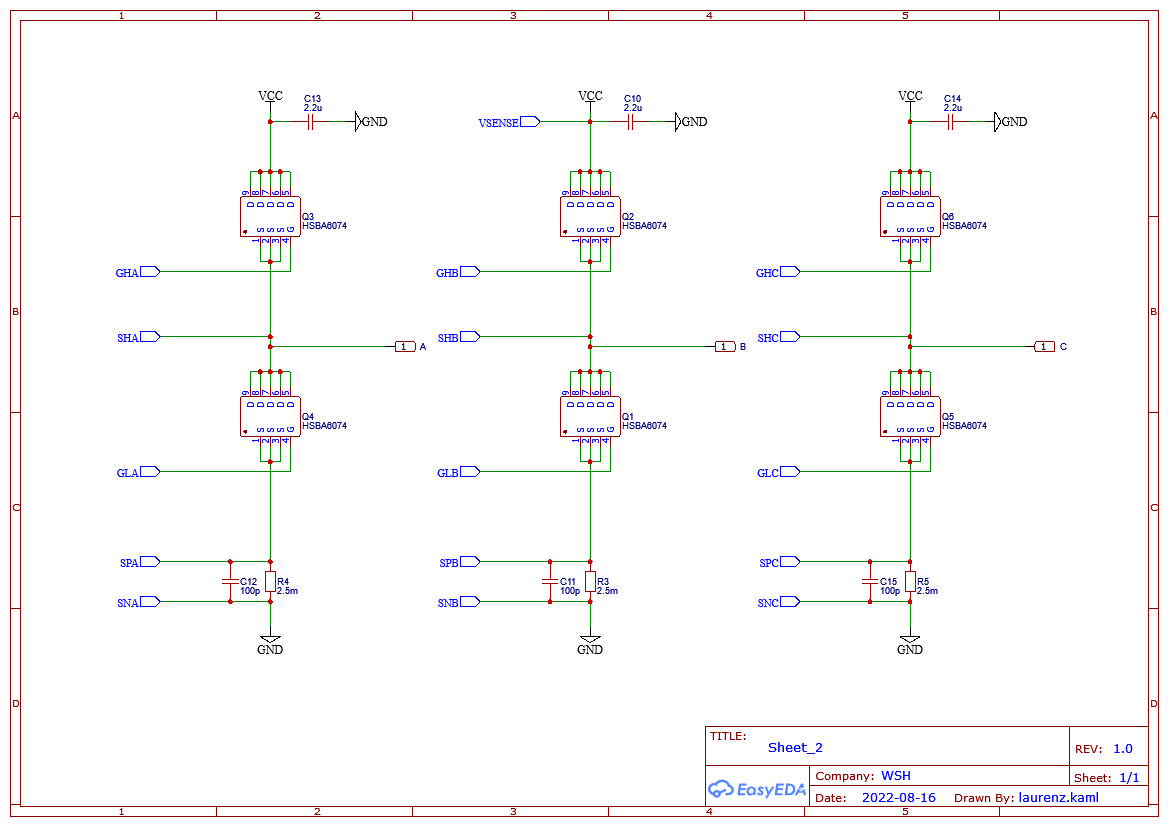
Finally I finished migrating away from the drv8305 to the DRV8323HRTAR (without SPI). This migration was a necessity due to the ongoing chip shortage. I also implemented the HSBA6074 FETS which @runger suggested. If anyone has additional input please let me know here
DRV8323HRTAR is also not in stock, and you cannot manually solder, it’s a WQFN package. I even tried the global sourcing, its completely out. Only Mouser have it, and they got about 100 left. By the time you read this the inventory may be gone completely.
For 40A continuous current you will need 2oz/4layer solid plates minimum with an impedance control and large heatsinks with forced cooling to dissipate about 80W at maximum current, or liquid cooling. Your PCB will be quite expensive.
As I said, you will be better off with large footprints (HYG050N13NS1B6) and a very common driver (IR2136STRPBF) as your first design. But you don’t have to listen to me of course.
I’m very curious to see the PCB layout.
Cheers,
Valentine
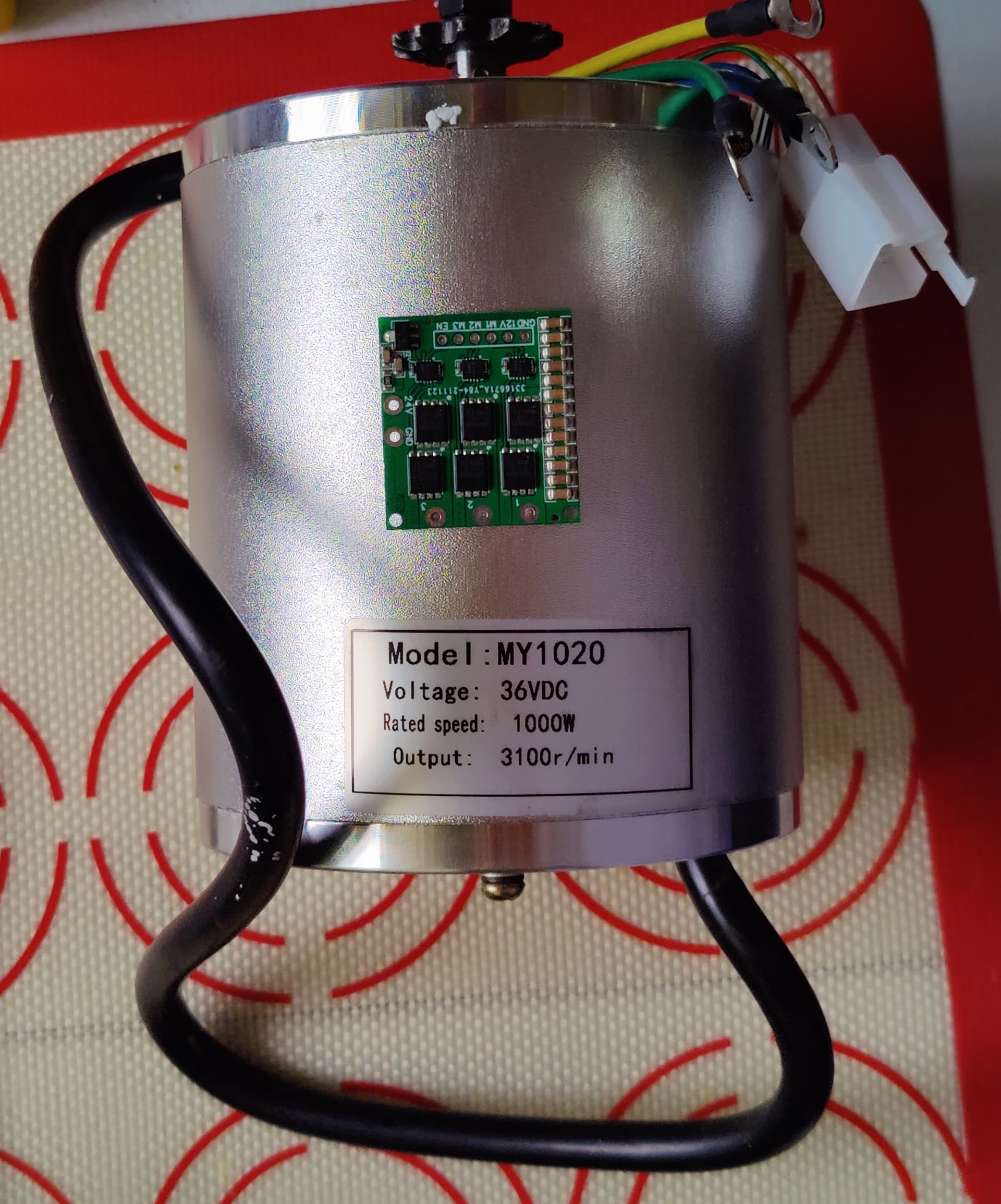
PS To give you an idea of what you are trying to achieve, this is a 1000W motor, along with one of my BLCD controllers I have built for a much smaller motor, with those same small MOSFETs you want to use as a comparison.
The motor is 1000W, and you want your board to push 1600W (40Vx40A) continuous current so you will essentially try to drive a 50% bigger motor with that same tiny mosfet. Do you really think this is a good idea?
When the cable connectors are bigger than your mosfets, I say you may want to go back and rethink your design.
If you ask me, you need something like that (that driver is built for the big motor above):
Hi @Valentine,
Your Krakatoa board might be what I have been looking for. I plan to put a 12 KW 3-Phase BLDC motor in my sailboat. I got the motor, but the controller was busted. It came fra an early Tink car. I also want regen, so I can charge the battery while I am sailing. The motor is rated for 100V and 100A. Are you selling the boards? Do you think it will be fine for the task?
I’ll leave it to @Valentine to comment on the capabilities of Krakatoa…
But I will say this: I think we’re a great library, but we’re a library for DIYers, and people who want to experiment and learn about BLDC motors and FOC. We’re not a finished product.
Depending on where and how you use the boat, your motor system could be relevant to the safety of you and your passengers. Please consider carefully before you take any risks.
Additionally, the power levels you’re talking about are really high, easily capable of killing a person. If you do this, please make sure to put in adequate protections, and if you’re not one yourself, get an electrician to look at it. 100A and water…
Hi @runger,
Thank you for your consern. I have several frends that are able to check and veryfy the safety of this, so I hope it will be OK. I have just ordered three boards (B-G431-ESC1), so I can test the Simple FOC and see if I will use it. I will test it in some smaler BLDC motors I got.
Let me get back to you on that. Short answer yes you can drive the motor, however as @runger mentioned entrusting your life to the hands of someone random on the Internet you’ve never seen may be a little too Mad Max.
What is the battery voltage you supply to the motor?
Krakatoa is not set for regen, unfortunately.
The power levels combined with salt water will easily make manufacturing the board really expensive. The board itself has no problem however the auxiliary work on cooling and protection in a marine environment will really put a dent on your budget. It’s one thing to put this in a car, rain water is not really conductive, another in a highly conductive and corrosive saltwater marine environment.
This is not a joke, I agree. The testing must be very thorough. I take absolutely no responsibility for that adventure. He should not be playing with his life like that.
As I said, this is really your decision. I suggest you buy a commercial package, however, at such voltage and power levels and also resistive to marine environment they will probably cost you in the $thousands .
Please let me know if you are still willing to risk your life.
Normal operation voltage will be in the range of 90 till 100V, the limit might be 85 till 105 volts.
That would be nice to implement. I like to have projects to work with and learn from.
Yes, this is a challenge. First it will be tested in my lab, so that will be without the salt.
How it will be implemented in the sailboat is not clear, but 3D printing a closed box with cooling might be an option. I have looked at liquid cooled pc.
Regen is something I know very little about, but I know what I want out of it.
When sailing above 5 knots I hope to get 100 watts back and maybe 250 watts at 6 knots and 500 watts at 7 knots. Maybe 0 watts at 4 knots.
My thoughts were to disengage the plus from the battery with a relay, and in gage a boost converter to get the generated power up to needed voltage for the BMS to be happy. When the battery is full, the propeller should spin freely so there should be minimum drag from the propeller.
This might be much to ask for, but we will see what we get.
The Krakatoa board was a study board. Do not manufacture it, it will not carry that current and voltage because the copper on the board itself is way too thin, and the driver will burn. To get to those voltage and current levels I need to redesign the board, which is not really a problem. The real problem is manufacturing the board. The board will cost about $500 for two boards for you to test, including destructive testing. Then we fix whatever needs to be fixed, and each new board is again about $250. At the end you will end up paying about $1000, not counting the shipment, import taxes, cost of testing, 3D printing, etc.
Let me know if you want to do this.
I cannot promise regen. I know more but don’t have money to design and test it. Regen design and testing requires me and @runger to collaborate and it literally may take months and also extra hardware I don’t have money to invest. If you want to invest into my time and materials I’m OK, we will set up some kind of funding (gofundme or whatever) and I can do it. Again let me know if you are OK with that.
What I need is just a controller board for the motor, and the possibility for regen. The low speed of the propeller during sailing will give very low voltage and a boost converter might be needed. In Norway we have a lot of electric cars and a lot of older cars that is been demolish, so it is possible to get hold of used motor controllers that is good for 400 or 800 volts and many hundreds of amperes. The problem is that the software is a black box, but they go for $500 to $1000.
Your offer might be more expensive and take 3 till 6 mounts. I was hoping to have this ready by May or June.
I need to see if I can find some used motor controllers or some other alternatives first before I commit to your suggestion.