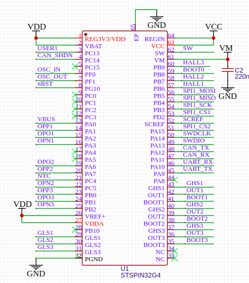
Hi @runger - both myself and @DarkMajster have designs loosely based on stspin32g4 eval board. This is a lowside design very similar to b-g431-esc1. i.e. using 3 internal opamp/comparator to measure shunts. Each phase has opp, opo, opn pins however I think 1 of the pins is different to b-g431-esc1.
Am I right in thinking I can lift and shift the b-g431-esc1 code with a few tweaks?
I did not do this comparison properly, but my impression is maybe the F4/G4 code is slightly newer than the G431 code.
So personally my approach will be to use the standard G4 current sensing code (low side) and add the OPAMP initialisation on-top.
My impression is Candas and others have done a lot to improve the STM32 current sensing code recently, but their focus was F1/F4/G4, and I have not checked to see if all the improvements also made it to the G431 codebase…
Longer term, I think the specific g431 code should be replaced anyways
@runger what is the “opamp init code at the top” that you talk about?
I’ve tried https://github.com/Candas1/Arduino-FOC/#stm32_adc_no_interrupt and normal simplefoc and am getting the following during setup:
@runger Please correct me if I am wrong.
All STM low side current sense drivers require the pins/channels to be on the same ADC, except the G431-ESC1 that is using 2 ADCs but is very hardware specific.
I started to work on a new setup with a nucleo-ihm16m1 and I have the same error message. I couldn’t investigate in details yet.
I am not sure if there are alternative pins that can let you pick the same pin on a different adc as a workaround ( see pinmap )
[EDIT] No PA2, PA6 and PB1 cannot be used with the same ADC it seems.
This would work with the G431 current sense driver, the pins are the same.
Ideally, the drivers should be improved to be able to initialize different ADCs if needed, but that could be complex.
So then for the moment you have to use the G431 code…
Longer term, the general STM32 code should work also with multiple ADCs, and the B-G431-ESC1-specific code should be reduced to configuring the OP-Amps which is the part that is unique to that board…
Generally speaking using different ADCs is actually better since the conversions can happen in parallel rather than sequentially. We’ll have to look over the code though to make sure the way we read the values in injected conversion doesn’t make it happen sequentially in the end…
I’m somewhat confused, @runger - you suggest I used G431 code but that doesn’t have any OPAMP configuration which is what I want as the stspin has OPAMP1, OPAMP2, OPAMP3 configured. So it looks to me like my board needs to use code similar to B-G431-ESC1. There are some things stopping me from simply setting -D ARDUINO_B_G431B_ESC1 (pretending to be that board)
OPAMP2 pins are a bit different on my board
b_g431_mcu.cpp has references to defines e.g. A_POTENTIOMETER that cause the code not to compile
I could start a new hardware specific folder for stspin32 (based on ESC1) - looking for some guidance on what might land best.
I’m sorry, I realise now that must be pretty confusing…
So the situation is this:
At the moment, you should certainly base your solution on the B-G431-ESC1 code. This both because of the OP-Amps, and also because it is currently the codebase that works with more than one ADC.
Please don’t start another hardware specific folder for STSPIN, that seems like the least preferable solution to me…
Longer term, in the future, both the B-G431-ESC1 and your STSPIN code should just be re-factored into the main G4 driver. There is nothing special about either of these hardwares, they are both standard G431s in terms of how their ADCs are configured.
Longer term, we should add some code to configure the op-amps. This is what is “different” in the B-G431-ESC to the standard current sensing code with no op-amps. So we should find a way to make it an optional add-on to the standard code.
We want to avoid a situation where each hardware combination becomes a new current sensing hardware folder in the main library. If anything, that would be for the drivers library, but even better would be a situation where different hardwares are just “examples” showing how to configure the standard driver…
Thanks all - I’ll probably start by forking and putting a bunch of additional defines in the existing b_g431 hal files until I get something working. Happy to try to shake out the OPAMP stuff too with guidance.
I also need one for the TIM_ETR signal, please, to implement the HWEncoder index pin
And the LPTIM timers are also missing from the PinMaps. There’s a lot of omissions, actually, but adding them to stm32duino is a big job due to the huge number of STM32 MCUs…
Perhaps it might be better, since these are STM32-specific concerns anyways, to just base the API directly on PinNames (PA_12_ALT1) rather than the Arduino pin numbers and avoid the translation problems from the outset, and not need any PinMaps.
I don’t know how they generate those maps… I hope it is not by hand, there are so many variants.
It would be possible to generate them somewhat trivially for all peripherals, although quite slowly, by using some tools like Tabula: Using Tabula to Parse PDF Tables – Vivonomicon's Blog
If you look in stm32duino there are a lot of extra scripts and cmake targets. I think they generate at least all the generic variants, but TBH I could not figure it out completely last time I looked into it.