Then i set current limit for 10A and stopped it while moving, It shows Iq=10A, but actually it takes about 0,5A from power supply (24V), did i do sth wrong?
Let me try to summarise the maths here, and if others can take a look at it and correct the mistakes I make, then together we should arrive at a good result
R_{shunt} = 0.005Ω I_{max} = ±10A
V_{drop} = 10A \times 0.005Ω = 50mV
If G is the gain of your amplifier, then:
V_{out} = G * V_{drop} +V_{offset}
Typically the offset is configured to be VDD/2. The offset will be found automatically by SimpleFOC.
So for this setup you could set the current sense parameters like:
LowsideCurrentSense(R_shunt, G, pinA, pinB, pinC)
So it actually looks correct the way you have it.
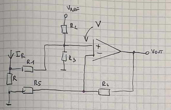
The gain of a non-inverting Op-Amp with negative feedback is given by:
G = 1+\frac{R_4}{R_5} (R4, R5 are your resistor numbers)
But that is not exactly the configuration you have? I’ll have to check it to see if R1, R2 and R3 change the gain.
To test the current amplification, I think the “stalling the motor” technique is maybe not the best. Not only is it a bit risky due to the high currents and forces involved, but as you noticed the current on the PSU vs. the current in the motor windings is not the same in this situation.
A better test would be the following:
on the software side, initialize the current sensing in the normal way, so the current sensing offsets get calibrated. You can use an incorrect gain value for now.
on the hardware side, after the calibration is complete, put the PSU into constant current mode, and supply a constant current of 1A or 0.5A - not too high, so nothing gets burnt.
on the software side, use digitalWrite() to directly set the gate outputs with no PWM. Set the driver gates so that current is flowing through one phase, e.g. UH = HIGH, UL = LOW, VH = LOW, VL = HIGH, WH = LOW, WL = LOW.
then use the current sense to read the current from phase B. It will be the DC current that you set on the PSU. Use this value to calibrate the current sense gain. You can print the value in the loop and adjust the gain until the value matches the one shown on the PSU. You can repeat for 0.1A, 1.0A and 2.0A to check the linearity. Personally, I would not run 10A DC current through the driver, even if your PSU can do it
Okay, so in the long run I’ll tune that gain to get same current measured in single phase as got from
current_sense.getPhaseCurrents();
right?
I got one more question, are voltages measured on shunt resistors in low-side measuring actually the same as phase currents? or you have to do some calulations with it?
Yes, you would tune the software gain value, until the value reported by getPhaseCurrents is the same as on the PSU.
If you have a good multimeter, you can put it in series and use the multimeter to measure the current, it will probably be more accurate than the PSU value.
By checking with different current values, you can see if the gain is the same across the range of currents, and find an average value if not.
By checking with different phases, you can average the results and reduce the error introduced by the resistor variations.
Well, the calculations are applying the offset and the gain, and converting from a integer value to a float value… but otherwise the value returned is the measured value across the shunt, like you need.
The important thing in this calibration experiment is that it is happening in a DC-current situation.
What’s more I passed 1A throught shunt resistor and with gain 8.33 i got correct measurement on
current_sense.getPhaseCurrents().
the more I’m surprised that 0,5A from power supply is 10A Iq? Or maybe it’s just because of PWM and coil and actually there are amperes flowing throught windings?
I don’t know - in the dynamic situation when the commutation is running on the windings, it is indeed the case that the voltage and current displayed on the PSU is not the same as the one on the motor. The power should be the same, but the voltage and current can be different.
But 0.5A to 10A is more than I would expect. Perhaps someone who knows the motor physics better than me can comment on it.
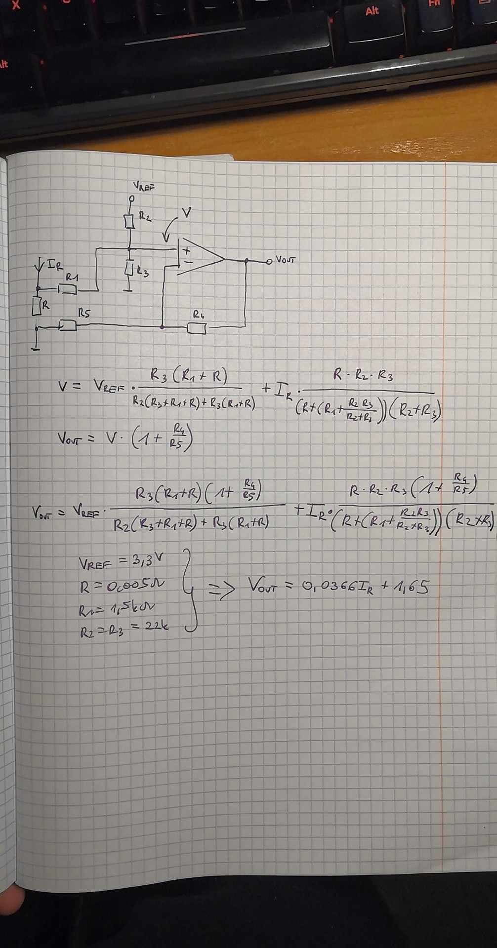
if current J goes throught Rshunt there is voltage V on it, after amplification by G it’s Vout=J * G * Rshunt
so IC to get J need to do J=Vout / (Rshunt * G)
in my case there is Vout=0.0366*J+1.65, so if IC do the same as above, will get:
0.0366 * J/(8.33 * 0.005)+(some const)=0.88*J+…
actually i should set G=0.0366/0.005=7.32 which is even more true relating to measurements