Hi @NES_U ,
Which part are you specifically having problems with understanding?
Is it the software side? The algorithms for BLDC driving with field oriented control (FOC) are somewhat complicated, is this your question? → SimpleFOC has you covered here, we provide software for driving the motor with FOC.
Is it the hardware side? Building a three-phase driver suitable for driving a small BLDC motor like from a hard-drive is not so difficult. Currents and voltages will be quite small, so you could even drive it without a dedicated driver.
If you want try this, you need to choose small FETs that are easy to drive.
Do you understand how FETs work? If not, you should read some documentation on it!
Your wish to drive the FETs without a proper driver is not an easy one, using the driver makes things easier, not more complicated…
This is because FETs and motor power are “power components”, usually using higher voltages than the MCU can manage. Interfacing them to the MCU is complicated.
For the low-side FETs, you can use N-Channel FETs, and maybe, if the gate charge is low enough you could even drive them directly from the MCU pin. The source of the MOSFET will be connected to GND (0V) on the low side, so a “on” signal from the MCU pins would be 3.3V, which is above the threshold voltage for switching on the FET. Most MCUs should be able to provide a few mA, which is enough to switch a small FET on quickly. The current should be limited with a series resistor (“gate resistor”), to make sure the MCU pin doesn’t give too much current and damage the MCU.
For the high-side FETs, it is more difficult: the high side FET’s source/drain pins can be at supply voltage. This voltage is outside the range of your MCU, unless the supply voltage is only 3.3V  For a hard-disk motor, it could be enough, but for most motors you will need 10V, 24V, or even much more, depending on the motor…
So for the high side, there is a problem:
- if you use P-Channel FETs, you can’t switch them off, because the supply voltage is higher than the MCU pin’s 3.3V
- and if you use N-Channel FETs, you can’t switch them on, because you would in fact need a gate voltage that is higher than the supply voltage.
So what to do? This why you normally need a driver to switch the FETs. Some things you can try:
-
Keep the supply voltage for the HDD motor <3.3V, i.e. use the same voltage for MCU and motor supply. Then you can use N-Channel FETs on the low side, and P-Channel FETs on the high side
-
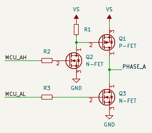
For higher voltages, use P-Channel FETs on the high side and another small N-Channel FET as a driver for the high side, like this:
Note that for this configuration the P-FETs Vgs rating has to be greater than your supply voltage, since you’re driving the gate directly from the supply.
-
Or use a proper driver