hello there
i am trying to build a self balancing bicycle(which is similar to inverted pendulum), and right now i’m trying to tune controller gains. i don’t know how to do it!
i have k1, k2, k3 for theta,theta_dot, phi_dot
theta: pendulum/bicycle angle
phi_dot: reaction wheel speed
what kind of principle should i follow to tune gains?
P.S: i know i should use lqr, but i don’t know exactly what i should do.
From the very little I know about this subject, find the low/high range of possible values and slowly start increasing them until you reach the desired behavior. A long long time ago in another life I did work on some very complex multidimensional optimization problems and creating a table of possible combination values and trying them all, then finding the best combination, then perturbing them once more on the high/low side, trying again, until you reach a local optimum, may be the best way to empirically approach the problem, short of analytically deriving a global solution which may be beyond your current capabilities.
Out of curiosity, are you using one or multiple motors? Do you tune the fork like that one?
thanks for the reply. that’s gonna take a looooonggggg time then!
i mean there are 3 gains, and i don’t know how to reach a good position in each gain.
for now i actually do not know if the behaviour i’m seeing is of untuned controller of of some other problems!
the idea u sent as a GIF was really interesting! really hit me but i’m doing it with reaction wheel like @REM666.
The reaction wheel is not the best choice in a system with more than one point of contact (fulcrum). You need to reduce it to a single fulcrum. If you remove the reaction wheel and instead connect directly to the rear fork you will instantly achieve a reduced mechanical feedback, using the rear wheel as a reference point. You are almost there.
With the reaction wheel, you will have to fight pretty complex nonlinear feedback because you also will want that thing to move around, so the gain needs to be adjusted dynamically, it won’t be fixed. You will always end up in a resonance area where the system will just go crazy instead of stabilizing. You could probably make it with a wheel but your wheel must be really heavy. Use the rear wheel as a second point instead.
Yes but you don’t have to solve analytically the problem
it’s my bsc project in university and it is set! i really can’t change it. all i’m trying to say is, if the cycle is not moving, it’s exactly like inverted pendulum in this video.
And truly to tune this one by hand. The rule of thumb is that the k1 should be higher than k2.
You can see the once you can see that it can kinda stabilise but the motor never stops rotating or the motor even slowly accelerates, reaches its max velocity and bicycle falls on a side then add the third term:
The k3 will force the motor to reduce it’s velocity and this term will avoid the motor constantly spinning when the bicycle is stable (or slow acceleration )
The rule of thumb is that k3 is the smallest one:
k1 > k2 >> k3.
thanks for the detailed response.
i will do that tuning soon. but it’s rather hard. since every time i should plug in the cable, upload the code. plug it out and test it. it’ll take forever. i’m thinking 3 min for each combination. i don’t know how long it’ll take
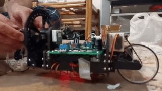
but i have other worries here. why is it rattling so much? is it normal? or i’m doing smth wrong? even though i don’t have any bolt and nut on the reaction wheel, it rattles aggresively. i’m not sure if this should happen. as soon as i put the bicycle down it starts rattling. i can’t even see how good are my gains. my gains where the same as inverted pendulum(and some othe values regarding k1>k2>>k3) but this rattling problem is still there
i will let the forum know what happens as i procceed
You can use the commander interface and change the gains online with the cable plugged directly.
Just add the k1, k2 and k3 to the commander as scalar variables and you will be able to change them through serial and see the influence right away.
I mean with the cable plugged in the dynamics is not 100% the same but it will give you a good idea if it is able to stabilise or not
The discussion about te ratting I am not sure I understand.
You mean the oscillations or some kind of mechanical play in the system?
the serial cable for Arduino is pretty stiff and the one that i have is not that long! i was wondering if there was a way to communicate with the Bluetooth module and the board
right now i have 2 Arduino Nano having separate codes. one has got a Bluetooth module on it while the other(which is for controlling the bldc) doesn’t have anything to communicate with except the serial port
so if there was a way to send some commands from Arduino #1 to Arduino #2. i would be able to change k1,k2, k3 with my app in cell phone directly. it’ll be easier
another way is to right a timed change for Ks, for example i can say after 500 loops, change k1, k2 , k3
and watch the bicycle behavior
about the rattle, yes i kinda think so. actually i don’t and i’m asking if this(structure of bicycle) is causing some kind of problem here. i sent a GIF but it didn’t come out well. i will try to send a full video by uploading it somewhere and put the link here soon:
In arduino bluetooth is usually handled as a serial communication interface and you can directly add it to the commander. This should work out of the box.
We cannot access the link I think, there is some kind of permission issue.