Sure, but here you have the 40us latency of the I2C bus + the internal latency of the sensor.
The internal latency of the magnetic sensors is much lower than this, so the result is propagated to the MCU on the ABZ lines with very low latency… but yes, the bandwidth can be a problem with these sensors also. Not all of them support high RPMs, and even the ones that do typically have some restrictions (like reduced accuracy).
Normally a I2C transaction involves writing the register and then reading the value. The AS5600 allows you to continuously read without setting the register address in-between. its internal logic resets the register after you read the second byte of data.
So you save an incredible amount of overhead by not performing the write, and not switching the bus between send and receive each time.
Yeah, I just made the simple update to the “read” member to proove the concept:
int MagneticSensorI2C::read(uint8_t angle_reg_msb) {
// read the angle register first MSB then LSB static int first = 1; // only request the write register once
Thanks!
What, if someone tries to use more than one sensor by multiplexing their CS lines, since they all use the same I2C address? You’d have to init each sensor once, but then it should work.
Yes, it will work, but the speed benefits will be gone. In fact, I don’t think most multiplexers will work for this.
Then you need to I2C write to the multiplexer, so you need to put a different address on the bus, write to multiplexer, and then write the sensor address again, so incurring the penally for switching between read and write again, and writing to a different device…
I you found a multiplexer with GPIO control then I suppose this would eliminate the need for the I2C writes, but I am still not sure I would recommend going down this road… I think it better to use 2 I2C buses, or to use SPI which works in this way by design.
I can manage to do the speeds up to 180rad/s, while with internal hall sensors I could go up to 400 without issue, have not tested above 400.
I think the control loop is loosing the ability to regulate speed, current rises quite fast as regulation fails.
Has anyone else had these issues?
To get AS5600 working above well above ~100 rad/s there are 3 things you can do (in priority order):
1-Change AS5600 filter setting. This requires using the non simpleFOC 5600 library
2-Change you IIC bus speed to the max supported by the AS5600
3-Change the simpleFOC as5600 lib to avoid overhead in command setting.
Instructions for all 3 should be in the thread above, and other threads.
If you do these 3 things, I believe you can hit 4K RPM. If you > ~5-10K, you need to use another sensor (MT6701 is my choice) as there’s some fixed delay you’ll never get rid of.
I2C frequency is set to 1MHz which is maximum supported.
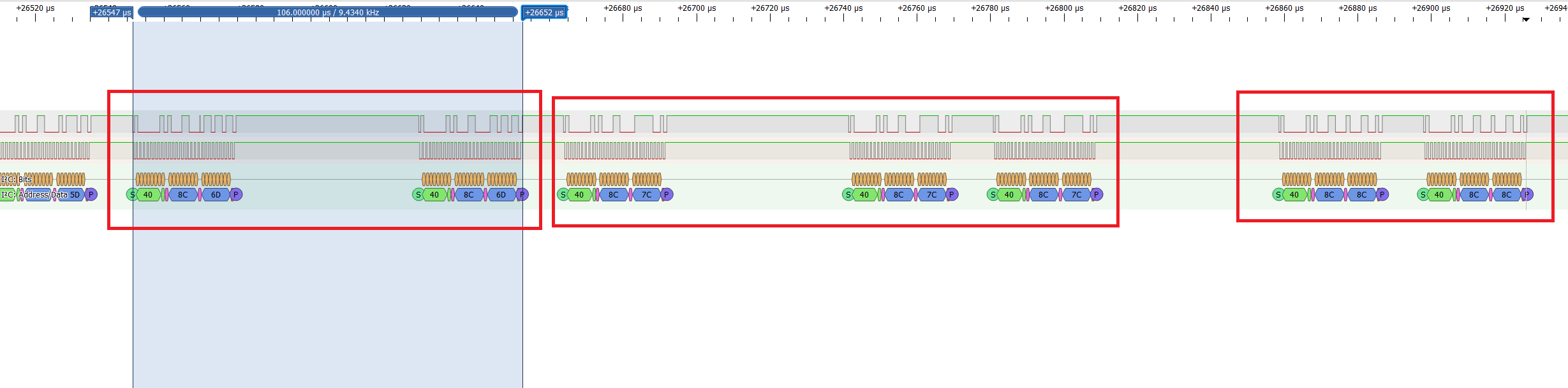
I think you are referring to continuous reading of the angle. I have done that, as you can see in my waveform capture.
But I am confused if the repeating data is normal and if that would be maximum update speed to raw angle. What do you think.
You can see decoded angle values in light blue on the last photo. See packages with same values?
Could it be that the shaft hasn’t moved enough to register a change?
If you’re running at 180 rad/s, thats about 28 revs/sec, or ~100000 counts/sec @4096 CPR, so you’d expect to see many updates over the 200us or so between your readings but clearly you’re not.
Here’s the thing though. I believe when you change the filter register, you might take a hit on the resolution so this could explain it.
I’d capture some of the I2c data in a buffer on your microcontroller and analyze the resolution and sample rate. Does your motor run well in closed-loop? If so, that means the data is coherent and timely, though with your low pole motor, you should be ablel to get more than 2K RPM (IIRC, I was able to get up to 5K with a 7 pole motor).
I have been operating in closed loop this whole time.
Basically I first tuned my PID controller using internal hall sensors. I was able easily to go to 400rad/s.
at 300rad/s my power consumption was 3.5W only.
Then i switched to magnetic sensor, at low rpm i am still good, up to 150rad/s, then current slowly increases and just shoots up. Above 180rad/s the motor is completely uncontrollable.
If I assume my motor is spinning with 300rad/s, and I read position every 100us.
That would give us an angle count increment of about 20 every read.
That increment would correspond to 1.7 degrees only at such high speed. So even if i read slower, or resolution is reduced, i could not understand why the control would be so unstable. For such speeds we should be plenty precise, right?
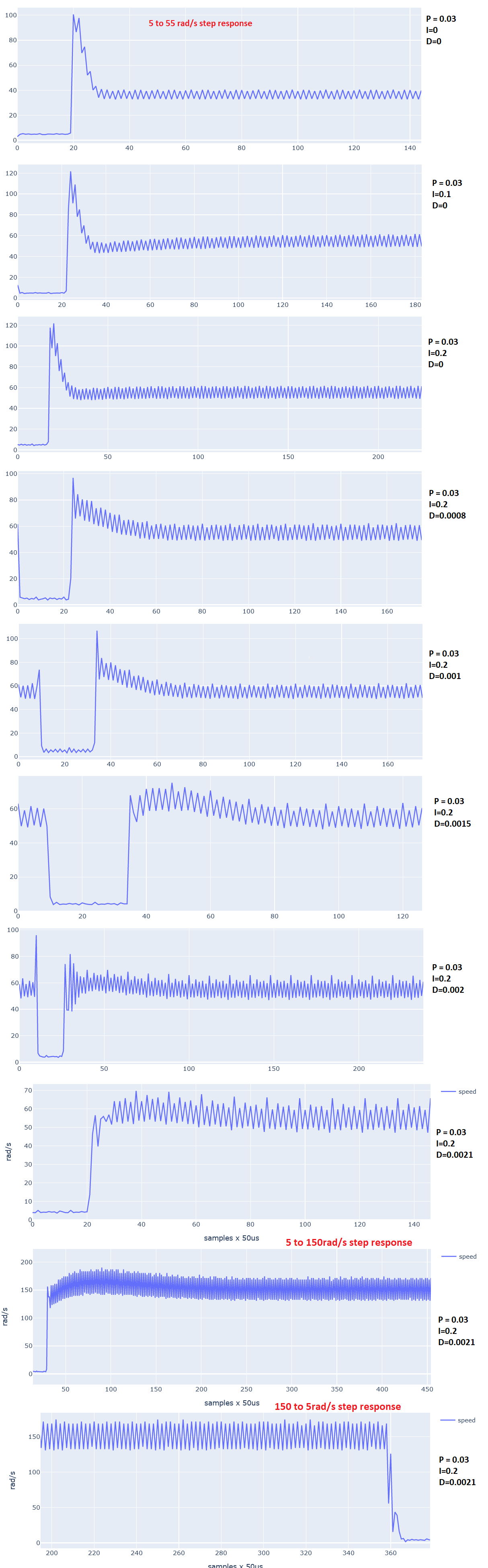
Using internal hall sensors for speed regulation, my motor runs fantastic. Check these curves
So i just captured some data.
With fast filters enabled, the resolution was not decreased.
I enabled fast filters and at very low velocity, and I can see the LSBs increment slowly and correctly.
When you see power increase at faster revs, this implies a fixed latency or delay on your rotatry measurement… Chaning to the fast filter greatly reduces this delay,
What I don’t understand is why in your case the delay is impacting you at 180, especially with a 4-pole motor. Is it possible that anything else could be delaying your loop? Did you post your code?
I did not post my code, but I just discovered an issue, and it was a silly thing indeed.
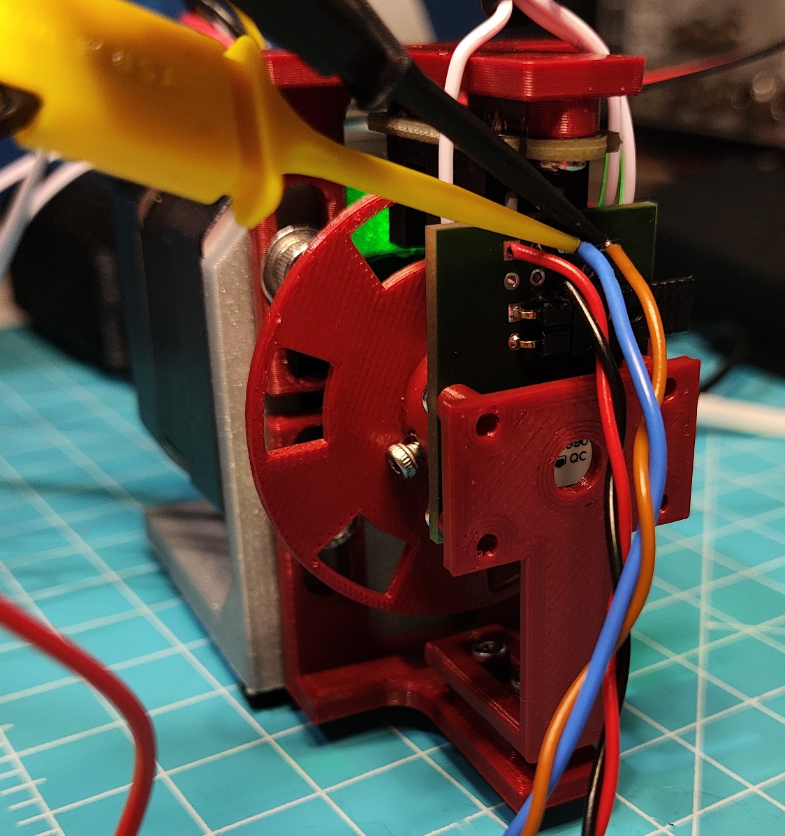
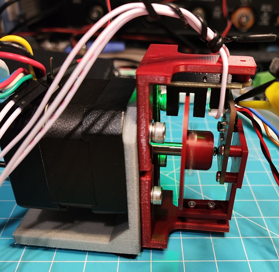
I think my sensor PCB was mounted very slightly off axis and it made a whole world of difference.
I need to 3d print a better solution to sensor pcb holder, and something more immune to vibrations as well.
I just moved it a bit and straighten it temporarily and it improved a lot.