Hello.
I’m currently using an Nucleo F446RE development board to get a small gimbal BLDC motor working for an heptic project I’m working on.
I’m starting in small steps and thought I would get the motor to simply spin, before I work out the poles and the rest of the calibration steps. For this I’m using the example code found on the Arduino IDE and the following link:
https://docs.simplefoc.com/bldcdriver6pwm
When I upload this code all my motor does is jump to a random position and holds that position.
I’m currently using the suggested TIMER1 pins:
BLDCDriver6PWM(PA8, PB13, PA9, PB14, PA10, PB15); //TIM1
I did try the TIMER 8 pins:
BLDCDriver6PWM(PC6, PA5, PC7, PB14, PC8, PB15); //TIM8
But this didn’t work at all.
I hope someone can point me in the right direction.
Arduino IDE wise I’m using the following:
Board set as: Nucleo-64 , F446RE
STM core: 2.2.0
BLDC Driver = TMC6300-BOB
Thank you for your time.
Hello @redknight106
Welcome to the forum.
Could you please post your hardware setup (driver, board, connections, motor) picture(s)?
Also please post the exact code you used. I know you said you used the example, but it may be some copy/paste issues?
Also, do you have an oscilloscope?
BLDCDriver6PWM(PA8, PB13, PA9, PB14, PA10, PB15); //TIM1
These are the correct pins for F446RE
Cheers,
Valentine
Hello, Valentine.
Thank you for the fast reply. I’ll sort out a basic wiring diagram but for the time being I’ll add the code I’m using:
/ BLDC driver standalone example
#include <SimpleFOC.h>

// BLDC driver instance
BLDCDriver6PWM driver = BLDCDriver6PWM(PA8, PB13, PA9, PB14, PA10, PB15); //TIM1

void setup() {

  // pwm frequency to be used [Hz]
  // for atmega328 fixed to 32kHz
  // esp32/stm32/teensy configurable
  driver.pwm_frequency = 50000;
  // power supply voltage [V]
  driver.voltage_power_supply = 10;
  // Max DC voltage allowed - default voltage_power_supply
  driver.voltage_limit = 10;
  // daad_zone [0,1] - default 0.02f - 2%
  driver.dead_zone = 0.02f;

  // driver init
  driver.init();

  // enable driver
  driver.enable();

  _delay(1000);
}

void loop() {
    // setting pwm
    // phase A: 3V
    // phase B: 6V
    // phase C: 5V
    driver.setPwm(3,6,5);
}
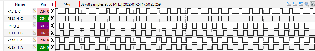
Luckily I have a logic analyser handy. It does like like all the channel are doing what I would expect.
Just abit confused why the motor is in a ‘stalled’ like position. Unless the TMC6300 isn’t suitable for my little motor.
The answer is very simple. This is not an open loop, you just forced the motor to hit a particular angle by setting the PWM to a specific coordinate.
What you need to run is the open loop example:
There’s nothing wrong with your setup. And having a logic analyzer really helps, thank you. The channels are doing exactly what you directed. You are almost there.
The only twist is that the open loop example has the 3pwm, you need to replace it with your 6pwm.
If I were you I’d definitely first read the entire section here before doing something that burns your nice setup.
Cheers,
Valentine
Hello, Valentine.
I have seen the error of my ways.
Thank you for clearing up my confusion. It’s now all working for me.
1 Like