I am having an issue with AS5600 (SEEED GROOVE) reading in I2C and PWM modes. In both connections, the angle and velocity values do not change.
My code in I2C mode:
#include <SimpleFOC.h>
#include <Wire.h>

// or quick config
MagneticSensorI2C as5600 = MagneticSensorI2C(AS5600_I2C);

void setup() {
  // monitoring port
  Serial.begin(115200);
  as5600.init();
  _delay(1000);
  Serial.println("AS5600 ready");
  _delay(1000);
}

void loop() {
  // IMPORTANT - call as frequently as possible
  // update the sensor values
  as5600.update();
  // display the angle and the angular velocity to the terminal
  Serial.print(as5600.getAngle());
  Serial.print("\t");
  Serial.println(as5600.getVelocity());
}
#include <SimpleFOC.h>

MagneticSensorPWM sensor = MagneticSensorPWM(A_HALL1, 4, 904);
void doPWM(){sensor.handlePWM();}

void setup() {
  // monitoring port
  Serial.begin(115200);

  //initialize magnetic sensor hardware
  sensor.init();
  // comment out to use sensor in blocking (non-interrupt) way
  sensor.enableInterrupt(doPWM);

  Serial.println("Sensor ready");
  _delay(1000);
}

void loop() {
  // IMPORTANT - call as frequently as possible
  // update the sensor values
  sensor.update();
  // display the angle and the angular velocity to the terminal
  Serial.print(sensor.getAngle());
  Serial.print("\t");
  Serial.println(sensor.getVelocity());
}
On the Arduino Mega board, this magnetic sensor works well. However, when I even try to connect to it over another sample (from SEEED repo) through B-G431B-ESC1, the sample is blocked on the detection (first I2C call).
I am using the sensor in 3.3V mode with 5V->3.3V drop-down (5V from B-G431B-ESC1). Checked the voltage on the input of the sensor, and it comes to around 3.3V.
On the Arduino board, I have used 3.3V output from the board.
Do not know where the issue might be, but I saw that people in this community have a problem with this particular sensor. Any help or hints is appreciated
Did you break the sensor board off the grove connector, or are you using the grove connector?
It’s a little unclear from the datasheet how the power scheme works. If you power it from 5V, probably the logic has to be 5V also… have you tried powering it with 3.3V only when connecting to the B-G431-ESC1?
I am using a Groove connection (the AS5600 board is not separated).
This AS5600 works in both 5V and 3.3V. I am using (tested) it in 3.3V mode on Arduino.
B-G431-ESC1 5V → 5V to 3.3V step down → AS5600 Groove connection VCC.
B-G431-ESC1 GND ---------------------------------> AS5600 Groove connection GND ( common GND pin step-down board).
B-G431-ESC1 SDL ----------------------------------> AS5600 Groove connection SDL.
B-G431-ESC1 SDA ---------------------------------> AS5600 Groove connection SDA.
(Schematic given in this post).
It seems to be simple, however, I am not able to make it work.
I am suspecting some 5V to 3.3V voltage regulator issue (it is a dedicated voltage step-down pin on the cheap logic converter) or maybe ‘burned’ input pins (i think one time i used this sensor in 5V mode and the input might be ‘burned’).
I will try to troubleshoot through the next few days by:
Changing the 3.3V voltage regulator.
I have ordered 2x ESC1 (it will arrive tomorrow or in 2 days), I will check if I am encountering an issue with the new controller (since my old one might have burned pins )
Sorry, and I understand that my provided information is quite generic and it is hard to comment and give hints based on it I saw that there are some issues with the AS5600 sensor (found in posts), wanted to hear your thoughts of people who might encountered something similar
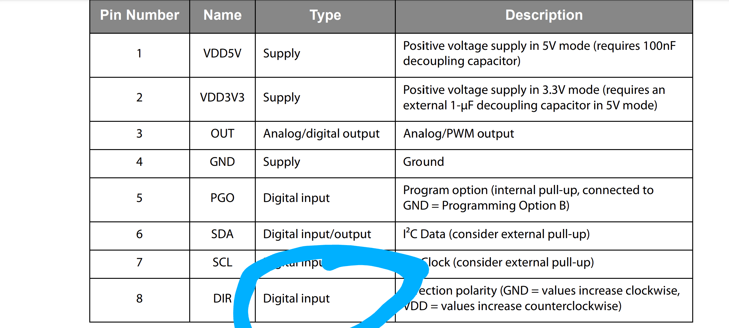
Hi all, I was struggling with an AS5600 breakout board today. I got similar I2C “fixed” 12.56 values and SimpleFOC gave up when no motor movement was detected. The fix for me was that DIR pin needs to be tied high or low voltage - it cannot be left floating otherwise this strange behaviour happens.