B-G431B-ESC1 problem with hall sensor

Looking at the schematic and the routing of the board there does not seem to be any connection between pin HALL1 and pwm output signals. I didn’t check with the multimeter, could you tell me what to check?

Continuity aka beep mode. Sometimes you can’t see the bridge, even if it’s right in front of you.

Edit: I’m not sayings it’s 100% the case, but maybe it is. Maybe it’s something inside the MCU, like a pin setting or something.

It could also be a bridge inside the motor, on the hall sensor itself or nearby.

Hay, did you consider if it’s the magnetic field of the coils triggering that one hall sensor, creating a PWM signal… from what I read 3.3k resistor on the hall’s is often used. 2k could be to low. Don’t know.

I don’t think the problem is the motor or the sensor. I tried to load the code on another board B-G431B-ESC1 without connecting the motor and the sensor and with the oscilloscope I read the same PWM signal. I will try to do more tests to find some hardware bridge, but maybe it’s more probable that is a software problem. However I am trying to find a possible solution in the library but I still haven’t found anything.

Hi @Mary-Mtrs,
You have to put a RC filter (pull up resistor + resistor (1K) + pull down capacitor (1nF will be enough), and that should work…

Or otherwise it is your firmware…

Hey, to help us understand the problem, would it be possible for you to provide a picture of the oscilloscope plot? I’d like to see if one can tell if it is noise or signal of the PWM we see on the hall signal line…

And if you could provide high-res photos of the top and bottom of the board, people might spot problems, if there are any visible ones.

On the software side, it could help if you could provide some of the code you’re running? If that is possible…

It would be interesting to get to the bottom of this!

That is strange, so we can rule out noise from the motor then. Are you able to use another input pin for that particular hall? Could be a fix, but will not show the cause…

Edit: I think your best bet is to let @runger look at your firmware.

Thanks everyone for your help! I show you the tests I have done. I am using the arduino ide and to install B-G431B-ESC1 board I used the instructions of @Wittecactus in beginner-guide-i2c-guide.
First of all, I ran the code related to open loop velocity control:

#include <SimpleFOC.h>

BLDCMotor motor = BLDCMotor(11);
BLDCDriver6PWM driver = BLDCDriver6PWM(PHASE_UH,PHASE_UL,PHASE_VH, PHASE_VL,PHASE_WH, PHASE_WL);

HallSensor sensor = HallSensor(HALL1,HALL2,HALL3,11);

void doA(){sensor.handleA();}
void doB(){sensor.handleB();}
void doC(){sensor.handleC();}
 
float target = 1.00; //[rad/s]

void serialLoop(){
  static String received_chars;
  
  while(Serial.available()){
    char inChar = (char) Serial.read();
    received_chars += inChar;
    if(inChar == '\n'){
      target = received_chars.toFloat();
      Serial.print("Target = "); Serial.println(target);
      received_chars = "";
    }
  }
}

void setup() {
  Serial.begin(115200);
  delay(1000);

  sensor.init();
  sensor.enableInterrupts(doA,doB,doC);

  driver.voltage_power_supply = 12.0;
  driver.init();
  motor.linkDriver(&driver);

  motor.voltage_limit = 1; //[V]
  motor.velocity_limit = 20; //[rad/s]
  
  motor.controller = MotionControlType::velocity_openloop;

  motor.init();
}

void loop() {
  serialLoop();
  
  motor.move(target);
  
  Serial.print(sensor.getAngle());
  Serial.print("\t");
  Serial.println(sensor.getVelocity());  
}


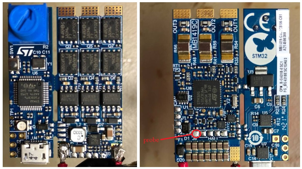
Attaching the oscilloscope probe to the HALL 1 pin I detected a PWM signal with a frequency of 25 kHz, with a variable duty cycle and with a signal amplitude of 2.2 Vpp:
pwm
I noticed that the PWM signal on pin HALL 1 is synchronized with the output signal related to phase 2 of the motor (green signal). Maybe this could be useful to find a possible bridge (hardware or software).
pwm+phase (2)
I also noticed that changing the value of the variable motor.voltage_limit changes the range of variation of the duty cycle. For example by setting the variable voltage_limit = 1 the duty cycle range is 42-57%.
I replaced the existing 10K pull up resistor with a 2.2K resistor and I obtained a decrease in the amplitude of the pwm signal on pin HALL1. This made it possible to avoid the increase of the number of false interrupts but did not actually solve the problem.

Secondly, I ran the code related to closed loop voltage control:

#include <SimpleFOC.h>

BLDCMotor motor = BLDCMotor(11);
BLDCDriver6PWM driver = BLDCDriver6PWM(PHASE_UH,PHASE_UL,PHASE_VH, PHASE_VL,PHASE_WH, PHASE_WL);

HallSensor sensor = HallSensor(PB6,PB7,PB8,11);

void doA(){sensor.handleA();}
void doB(){sensor.handleB();}
void doC(){sensor.handleC();}
 
float target = 1; //[Volt]

void serialLoop(){
  static String received_chars;
  
  while(Serial.available()){
    char inChar = (char) Serial.read();
    received_chars += inChar;
    if(inChar == '\n'){
      target = received_chars.toFloat();
      Serial.print("Target = "); Serial.println(target);
      received_chars = "";
    }
  }
}

void setup() {
  Serial.begin(115200);
  delay(1000);

  sensor.init();
  sensor.enableInterrupts(doA,doB,doC);

  driver.voltage_power_supply = 12;
  driver.init();
  motor.linkDriver(&driver);
  
  motor.voltage_limit = 1; //[V]
  motor.velocity_limit = 20; //[rad/s]
 
  motor.linkSensor(&sensor);

  motor.voltage_sensor_align = 1; 
  
  motor.torque_controller = TorqueControlType::voltage;
  motor.controller = MotionControlType::torque;
  
  motor.useMonitoring(Serial);
  motor.monitor_variables = _MON_TARGET | _MON_VEL;
  
  motor.init();

  motor.initFOC();

}

void loop() {
  serialLoop();

  motor.loopFOC(); 
  motor.move(target);
  
  motor.monitor();
}

In this case the alignment phase seems to work but when the alignment is completed the motor does not move whatever the reference voltage value is.
Cattura
Also I tried to skip the alignment step by entering the obtained parameters in the initFOC function:

motor.initFOC(1.05,Direction::CW);

The motor still does not move but I have read on pin HALL1 a pwm signal with fixed duty cycle.
I add a complete image of all the connections, where orange is HALL1, yellow is HALL2 and white is HALL3 (I also checked the welds with a microscope):


@runger, I hope I was clear! Are there any other codes/informations I can share?

Wow, that is weird… either there is an electrical connection between phase B and Hall 1, or its a mysterious software bug where the PWM of phase B gets output to hall 1, PB6.

To check the electrical connection, measure the resistance (or even better, use beep mode) using a multimeter between pins PA9 (phase B high) and Hall 1 and also PA12 (phase B low) and Hall 1. Either of these signals could be the culprit, since PA12 is the same PWM as PA9, just inverted, so from the looks of your oscilloscope, it is probably PA12.
You can check the pins directly on the MCU with a fine probe, or on the driver’s input pin, but I guess you already did this to get the green plot.

To check the software, lets see what’s going on:
PA12 is TIM1 channel 2N (inverted channel 2). PA9 is TIM1 channel 2 - neither of these channels is on PB6, and in fact TIM1 is not on PB6. So PB6 can’t really be outputting the PWM signal.

You code looks ok to me - I can’t see where PHASE_UL, PHASE_UH, etc are defined, but I assume they are correct? Could you check their definition to be sure?

As a comment regarding the initialisation, don’t use the ASCII float value 1.05 - it is rounded. While it could be exactly 1.05, maybe it is also 1.04555 - if possible, use the exact float value returned, or print it to 3 or 4 decimal places.

I checked for the electrical connection and there doesn’t seem to be any problems.

I added the following files created by @Owen_Williams: PeripheralPins.c, PinNamesVar.h, ldscript.ld, variant.cpp, variant.h
In particular PHASE_UL , PHASE_UH, etc are defined in the variant.h file

I am not sure if it helps, but the installation procedure described by Owen is not required anymore since his work is now part of the standard Arduino environment. Just select " ST B-G431B-ESC1 Discovery" as board type and everything should be set. However, note that you will have to rename the defines in your code to e.g. (note the A_!):

BLDCDriver6PWM driver = BLDCDriver6PWM(A_PHASE_UH, A_PHASE_UL, A_PHASE_VH, A_PHASE_VL, A_PHASE_WH, A_PHASE_WL);
InlineCurrentSense currentSense = InlineCurrentSense(0.003, -64.0/7.0, A_OP1_OUT, A_OP2_OUT, A_OP3_OUT);
Encoder sensor = Encoder(A_HALL1, A_HALL2, 1024, A_HALL3);

Perhaps, your existing configuration is ok too, but using the standard files from the framework is simple and should be on the safe side.

  • Chris

Since there is no electrical connection I guess it has to be a software problem. Either that or a broken STM32 chip.

While the definition files you link to look correct, perhaps there is a subtle incompatibility between these files and the official framework ones. Also because the framework has been through several upgrades since Owen created those original files.

So I agree with @Grizzly , first thing to do is to change the project to use the official board setup from the STM32 framework. If the problem still exists then, we look further into it.

I installed the library again following the procedure on the SimpleFOC website. I ran the code related to open loop velocity control and I noticed that the PWM signal seems to have disappeared. However I have not solved the problems related to closed loop voltage control because after the alignment the motor does not move.

#include <SimpleFOC.h>

BLDCMotor motor = BLDCMotor(11);
BLDCDriver6PWM driver = BLDCDriver6PWM(A_PHASE_UH, A_PHASE_UL, A_PHASE_VH, A_PHASE_VL, A_PHASE_WH, A_PHASE_WL);

HallSensor sensor = HallSensor(A_HALL1, A_HALL2, A_HALL3,11);

void doA(){sensor.handleA();}
void doB(){sensor.handleB();}
void doC(){sensor.handleC();}
 
float target = 1; //[Volt]

void serialLoop(){
  static String received_chars;
  
  while(Serial.available()){
    char inChar = (char) Serial.read();
    received_chars += inChar;
    if(inChar == '\n'){
      target = received_chars.toFloat();
      Serial.print("Target = "); Serial.println(target);
      received_chars = "";
    }
  }
}

void setup() {
  Serial.begin(115200);
  delay(1000);

  sensor.init();
  sensor.enableInterrupts(doA,doB,doC);

  driver.voltage_power_supply = 12;
  driver.init();
  motor.linkDriver(&driver);
  
  motor.voltage_limit = 1; //[V]
  motor.velocity_limit = 20; //[rad/s]
 
  motor.linkSensor(&sensor);

  motor.voltage_sensor_align = 1; 
  
  motor.torque_controller = TorqueControlType::voltage;
  motor.controller = MotionControlType::torque;
  
  motor.useMonitoring(Serial);
  motor.monitor_variables = _MON_TARGET | _MON_ANGLE;
  
  motor.init();

  motor.initFOC();

}

void loop() {
  serialLoop();

  motor.loopFOC(); 
  motor.move(target);
  
  motor.monitor();
}

Do you have any suggestions?

There is something wrong but I don’t know what! After installing the library again, I printed the pins of A_PHASE_UL, A_PHASE_UH, etc and I noticed that A_PHASE_WL is 207 instead of 23. I tried to change this value but nothing changed. Moreover, during the alignment phase I always read the following messages on the monitor:
Cattura
So I wrote in the function the value of the offset and the direction

motor.initFOC(1.0472,Direction::CW);

and I printed the target and angle on the monitor. I always read as angle 0.0945 and the motor does not move for any voltage reference. By increasing the reference voltage value, the absorbed current increases but the motor does not move. I’m starting to think that the problem is in the alignment phase or the problem could be the motor or the sensor.

Good news! The board I was using probably had some weird problem. I changed the board and now the closed loop control works! thanks everyone for the help

2 Likes

You are lucky… I have two boards here with the same PB6 issue - so i can confirm the same behavior - so it must be a wrong batch… It took me a week to finally go here.

Solution for this issue is provided here:
https://community.st.com/s/question/0D53W00001rrUbESAU/evspin32g4-hall-h1-on-pb6-is-being-pulled-to-2v

Add
HAL_PWREx_DisableUCPDDeadBattery();
or
SET_BIT(PWR->CR3, PWR_CR3_UCPD_DBDIS);

resolve this issue.