You should understand that a motor-driver works just like a switched-mode powersupply (SMPS). It can transform voltages and current. It transforms 24 volts at 4 amps into 6 volts at a much higher current. There is also the problem that meter-readings cannot be trusted if the current is not pure DC. It might read peak or average or anything in between.
Thanks @Owen_Williams for all the information you have shared about SimpleFOC in combination with the B-G431B-ESC board.
Have you ever tried to get USART1 or USART3 to work on the B-G431B-ESC? I am now looking into getting USART3 to work by doing the following:
PC10 button → USART3_TX
PC11 CAN_SHDN → USART3_RX
PB9 CAN_TX → USART3_TX
I am using USART2 to communicate between an Arduino nano over software serial. However this is only half-duplex I think. So I can either receive or write code. For debugging it is handy to also be able to read out the B-G431B-ESC via USART3. Do you think this is possible?
Hi all,
thanks to all the info here and after some testing I managed to setup such an esc. My problem (now ![]() ): Phase V is missing. See plot (try to upload separately, doesn’t work in that replay). I have two of those boards and after I run into that problem with the 1st I tested the 2nd out of the box and it shows exactly the same behaviour / bug. So unlikely that two new kits have the same HW bug …
): Phase V is missing. See plot (try to upload separately, doesn’t work in that replay). I have two of those boards and after I run into that problem with the 1st I tested the 2nd out of the box and it shows exactly the same behaviour / bug. So unlikely that two new kits have the same HW bug …
I don’t see really what can go wrong. I looked into examples and copied the one, tried open loop 1st. I needed to change pin names to A_… but everything seems to be connected to the timer channels correctly:
BLDCDriver6PWM driver = BLDCDriver6PWM(A_PHASE_UH, A_PHASE_UL, A_PHASE_VH, A_PHASE_VL, A_PHASE_WH, A_PHASE_WL);
Does anyone have an idea?
Thanks!
don’t manage to upload a jpg … not my day today.
But I can clearly measure with an oscilloscope that phase U,W have voltage output as expected but phase V hasn’t.
Is there any way you could check if the MCU pin itself is outputting the PWM signal? I know the board is really tiny, so just asking.
yes, it’s really tiny… but maybe possible on the high/low drivers. That is the biggest package on the board. Will check schematics tomorrow. But I wouldn’t expect something different than on the H bridge output. Where should that come from…. But I will look a bit more in the oscilloscope….
At that point I’m wondering if anything could be damaged by ESD, so to make sure the problem is really the MCU not putting PWM on the pins. Yes, this is a very tiny board, you would need a needle probe and a magnifying glass.
I will try to do. I have all what I need for that. I will mask the neighbor pins with tape to make sure I don’t short something. But I ruled that out after I saw exactly the same behavior on the same output on one relatively new board and on a brand new one that I took out of the package…
If you can reproduce it then its in the code for sure.
Good morning!
If it is a software problem, we will try to investigate it!
- which environment are you using, ArduinoIDE?
- could you post some details of your code?
- are you able to try it with the dev branch of the SimpleFOC library from GitHub?
Hi! Thanks for the questions!
I am using VSC with platfomIO in that project. I am not using ArduinoIDE anymore since it is so difficult to trace back the code. I have normally everything updated.
Regarding the code: what part would be helpful to share? The driver assignment I posted in the 1st description. I started with an STM32F103 and a simplFOC board (and you gave me that valuable hint with the lib_archive… ![]() ) and have last week changed from that to b-g431b-esc1 and made it simple with velocity open loop. Yes, I could use dev branch.
) and have last week changed from that to b-g431b-esc1 and made it simple with velocity open loop. Yes, I could use dev branch.
This is the platformIO.ini:
[env:disco_b_g431b_esc1]
platform = ststm32
board = disco_b_g431b_esc1
framework = arduino
monitor_speed = 115200
lib_archive = false
build_flags =
-D PIO_FRAMEWORK_ARDUINO_ENABLE_CDC
-D HAL_OPAMP_MODULE_ENABLED
-D PIO_FRAMEWORK_ARDUINO_NANOLIB_FLOAT_PRINTF
-D SERIAL_UART_INSTANCE=2
;-D PIO_FRAMEWORK_ARDUINO_USB_HIGHSPEED_FULLMODE
lib_deps=
askuric/Simple FOC
SPI
Wire
Pls let me know what other code / data would help to get an idea about the problem.
Thanks!
Hi Valentine,
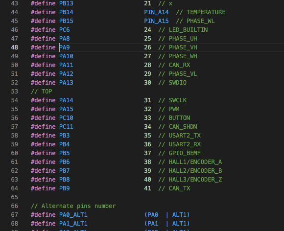
I tested on the pins of the L6387ED`s and I can clearly see that on U and W phase both inputs are actuated but on the V phase the H side is missing and constant at 3.3V. The L side is actuated correctly. so something is hindering PA9 = TIM1_CH2 to work as intended but TIM1_CH2N is behaving as it should.
I will surfe a little in the code and CubeMX to see what it could be but most likely I need help ![]() Thanks!
Thanks!
This is really strange, because the two channels are complementary.
Which pin is the TIM1_CH2N connected?


I checked the PDF manual, so pin mapping seems correct

Could you print the values of all the pins? I’m shooting in the dark here, but his is some timing issue with the way the MCU is being programmed.
BLDCDriver6PWM(A_PHASE_UH, A_PHASE_UL, A_PHASE_VH, A_PHASE_VL, A_PHASE_WH, A_PHASE_WL);
Print all values for A_PHASE_xx etc, as integers, so we see what the 6PWM sees. At some point they all translate to raw integers, let’s see if they match the integers from the documentation.
Hmmmm… very strange!
If find it best to use the STM32 pin names like PA9 , PB6 etc… rather than pin-numbers when working with the STM32 core. Using the Arduino pin numbers adds an extra layer of confusion. But if you have pre-defined constants like you do, that’s probably the clearest way.
PA9/PA12 should be working, as you have verified in the docs…
PA9 is also used in I2C2 and USART1 - are you perhaps initialising either of these peripherals?
Could you share PeripheralPins_B_G431B_ESC1.c? Check in HALL_TIM_MODULE_ENABLED if any of the pin configurations are commented out.
At that point it would be best to run a bare bones, simple open loop, no extra setup, not even Serial setup and calls. And plug in the direct reference to the pins, such as
BLDCDriver6PWM(PA8, ???, PA9, PA12, PA10, PB15)
Not sure/remember what’s the ??? pin however.
Also, I believe I posted a barebones code here at some point in the past, try running that?
https://community.simplefoc.com/t/b-g431b-esc1-beginner-guide-i2c-guide/515/17
This is perhaps some pin mapping issue.