B-G431B-ESC1: Beginner guide + I2C guide

Hi all,

This is a beginner guide for how to setup the B-G431B-ESC1 with SimpleFOC.

The B-G431B-ESC1 is a small but powefull esc at a great price point. More information on the specs can be found on the site of ST.

The board consists of main board (the ESC) and a daughterboard which is actually a programmer. This can be seen at the figure below:

Step 1: Install PlatformIO
This board is the most easily configured in PlatformIO. You can follow the install instructions of PlatformIO here and a great video of the installation made by @Owen_Williams can be watched here.

Step 2: Add board
Once PlatformIO is configured, the board needs to be added. This board is not a standard board so it needs to be added manually. Therefore the following files made by @Owen_Williams need to be added to the following folders:

  1. Go to C:\Users\wittecactus\.platformio\packages\framework-arduinoststm32\variants\
  2. Copy the folder called board_template and name it DISCO_B_G431B_ESC1
  3. Add/replace the following files: PeripheralPins.c, PinNamesVar.h, ldscript.ld, variant.cpp, variant.h
  4. Go to C:\Users\wittecactus\.platformio\packages\framework-arduinoststm32 and update the boards.txt file
  5. Go to C:\Users\wittecactus\.platformio\platforms\ststm32\boards and add this json file.

Now the board is configured.

Step 3: Run your code! :slight_smile:

Open a new project in PlatformIO. Select your newly configured board. PlatformIO works a bit differenty from the standard Arduino IDE. You put your arduino code in src/main.cpp and configure the libraries in platformio.ini . It is important that you put the following code in your platformio.ini file to make the board working and have serial communication:

Platformio.ini code:

;   Library options: dependencies, extra library storages
;   Advanced options: extra scripting
;
; Please visit documentation for the other options and examples
; https://docs.platformio.org/page/projectconf.html

[env:disco_b_g431b_esc1]
platform = ststm32
board = disco_b_g431b_esc1
framework = arduino
monitor_speed = 115200

build_flags =
    -D PIO_FRAMEWORK_ARDUINO_ENABLE_CDC
    -D PIO_FRAMEWORK_ARDUINO_NANOLIB_FLOAT_PRINTF
    -D PIO_FRAMEWORK_ARDUINO_USB_HIGHSPEED_FULLMODE

lib_deps=
    askuric/Simple FOC @ ^2.0.2
    SPI
    Wire 

For your main code do not fotget:

  1. To add #include<Arduino.h> to your sketch (for platformIO)
  2. Use the following 6PWM driver setup: BLDCDriver6PWM driver = BLDCDriver6PWM(PHASE_UH, PHASE_UL, PHASE_VH, PHASE_VL, PHASE_WH, PHASE_WL);

The rest is regular SimpleFOC code! Watch the following guide from @Owen_Williams for more information to make your first SimpleFOC code. For extra information check the datasheet and the following topic.

I hope that I can help some people with this guide! If the real pro’s want to add something or correct me somewhere just say it! Good luck everyone!

Sidenote: I hope to update this guide soon with I2C support.

Greetings,

Wittecactus

8 Likes

Hi all,

I2C Guide

This small update is for getting the I2C working on the B-G431B-ESC1. It is still a bit experimental and sometimes buggy so I will update it again when necessary.

Hardware:

Solder the following pads:

Hardware

It is recommended to use pull-up resistors.

Software:

In the file PeripheralPins.C, uncomment the following lines:

Uncomment

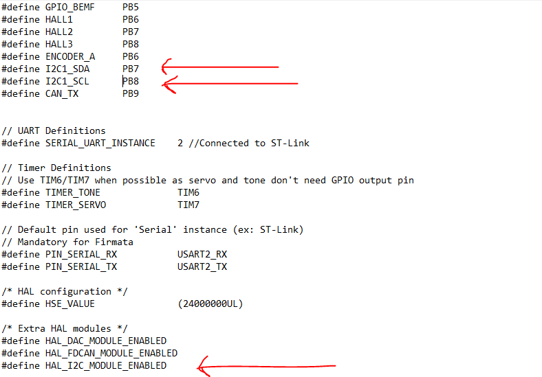
In the file Variant.h, change or add following lines (sometimes also works when you leave out this step but this seems to be more consistent.

Add

Then in your platformio.ini file you must remove the build flags from the previous post and the following flags:

build_flags =
    -D PIN_WIRE_SDA=PB7
    -D PIN_WIRE_SCL=PB8

Other tips:

  • Use the Platform.IO: Clean button to be sure that you are working with a clean configuration.
  • Sometimes it can be useful to add the build flags from the previous post.
  • Sometimes it can be useful to add Wire.setClock(400000);.
  • First add power to the board, then connect it with USB.
  • Remove power when uploading new sketch.
  • To get accurate sensor data, check with external power supply instead of USB power.

Greetings and good luck,

Wittecactus

3 Likes

@Wittecactus - great writeup!
I’ve pushed your changes into my PR (to stm32duino) with this commit. When the PR gets merged your changes will be part of the board definition.

I’ve been thinking about your intermittent i2c problem and I think the hall pullups (10K) are not sufficient for SDA/SCL. Did you add additional pullups externally? You can test this out by pushing a couple of 2.2 or 4.7K into your 2.54mm connector that I can see in your picture.

1 Like

Hi @Owen_Williams,

Really cool to see the changes added! :slight_smile:

Yes I added 4.7K external resistors! It looks like when the power comes from the power supply that everything works fine, but when using power from usb, then the sensor gives incorrect velocity data. For now it is fine.

Greetings,

Wittecactus

Hi All!

!!! EDIT: Most of these steps are not necessary anymore because the board is added to STM32duino for arduino IDE already, it will remain here for people who want to add the board manually !!!

Past month was a frustrating experience for me. I had lots of inconsistencies when uploading code from Platform.IO. Sometimes codes that worked the other day, would not work anymore the other day. After watching a video from Andreas Spies about debugging, he also said that he had some inconsistencies with Platform.IO. So I switched back to Arduino IDE and almost all inconsistencies seem to be gone (for now?).

Platform.IO has many advantages, but if you have the feeling that 80 percent of your time is going into making code runnable and you do not know anymore how to fix it? Then maybe this guide can be something for you!

B-G431B-ESC with Arduino IDE guide:

  1. Go to Arduino IDE -> Preferences -> Additional Board URL and add the STM32duino library: https://raw.githubusercontent.com/stm32duino/BoardManagerFiles/master/STM32/package_stm_index.json

  2. Go to Arduino IDE -> Tools -> Boards -> Boards Manager
    and install STM32 Cores

  3. After that open file explorer and go to:
    C:\Users\wittecactus\AppData\Local\Arduino15\packages\STM32\hardware\stm32\1.9.0\variants

  4. Make a new folder there and name it DISCO_B_G431B_ESC1

  5. Add/replace the following files created by @Owen_Williams : PeripheralPins.c , PinNamesVar.h, ldscript.ld, variant.cpp, variant.h

  6. Go to:
    C:\Users\wittecactus\AppData\Local\Arduino15\packages\STM32\hardware\stm32\1.9.0 and and update the boards.txt file

  7. Download driver for Windows (available here) and update the ST-Link adapter to the latest firmware (application to upgrade the firmware).

  8. Download STM32CubeProgrammer

The board is now fully installed and operational. When uploading use the following settings:

Settings

You can now use Arduino IDE and the B-G431B-ESC1 board. It made programming a lot easier for me .

I hope to update the guide soon for full-FOC mode. :slight_smile:

Greetings,

Wittecactus

Usefull links:

#Edit 1: Added missing step, thanks @Valentine!
#Edit 2: Added warning because board has been added in STM32duino 2.0

2 Likes

Hey @Wittecactus,

I’m also using the Arduino IDE with your configuration (thanks for the explanation on how to do it). However, I’m testing the example “angle_openloop” but I can’t send any command through the UART port. I’m using the last version of the library and the B-G431B-ESC1 board with its st-link.

Greetings,
Edgar

Hi @Edgar_Pisano,

That is strange. Everything else is working fine? I did not have this problem but here are some things to try out:

  • Check in a simple arduino sketch that commands via serial is working. Than we can exclude that it is code related.
  • Check that the ST-link firmware is up-to-date.
  • Check the upload settings.
  • Maybe a stupid one but I will add it to be sure: with the latest SimpleFOC update, you need to type T before your desired anlge position.

This is all that I can think of at the moment. Can you report to me back if one of the suggestiongs did the trick? Because if it did not do the trick, I will do a clean installation on my old laptop this weekend to see that I maybe forgot a step in the guide!

1 Like

I tried again on Platformio and it is working (with the T). Tomorrow, I will try again it on the Arduino IDE. I will let you know if is working :thumbsup:.

Do you have some experience with ROS? I would like to write a package for ROS but I’m having problems with the connection between computer and board. I trying to write a workaround for rosserial but at the moment I’m not so skilled in this kind of topics.

Greetings

Edgar

Ps: thanks for the answer

1 Like

Hi @Edgar_Pisano,

No problem! Great work! I also hope it works on Arduino IDE! :slight_smile:

ROS is still on my bucket list. I am hoping to follow some courses in it next year. ROSSerial can be a possibility. If I would implement ROS some day in the far future for my robot, I was planning to use CAN communication with an Rasberry Pi and a CAN module. I do not know exactly what your plan is with the board and ROS but maybe it could also be a possibility were you can look into!

My B-G431B-ESC1 seems to be working great with the Arduino IDE following these steps :slightly_smiling_face:. I managed to get the AS5048A magnetic sensor working in PWM mode as well (connected to the HALL1 pin) by creating a new sensor type heavily based on the existing MagneticSensorAnalog .cpp and .h files. I am getting some oscillations in closed loop velocity/position control modes at low speeds, but I imagine that is mostly due to lack of proper tuning and a relatively high kv motor (650kv).

Thanks for the guide!

1 Like

Nice work @JordanCormack - Perhaps you’d like to submit your MagneticSensorPWM sensor as a pull request so that others can use it?

You might want to play with the motor.LPF_velocity.Tf e.g increasing it a little e.g. from 0.005 to 0.05. Ideally you want to keep Tf low but If you are mostly constant speed you can increase it a fair bit.

Great work @JordanCormack! Nice to see that many people are experimentating with FOC and this board :slight_smile:. What kind of max speeds are you getting with this sensors? My speed is max around 60 rad/s what is not the desired speed I want so I was looking to get full FOC - current mode working.

I was curious if there are people who already managed to get FOC - current mode working on this device?

I am already stuck at getting the current sensors working. Looking at the datasheet it is using 0.003 ohm shunt resistors. Only the amplification gain is a bit more difficult because is using the internal op amps of the chip itself.

These internal op amps can be enabled with a HAL module. Only problem is that is not a simple HAL module that can be turned on or off like I2C. This HAL module needs first to be configured before it can be enabled. I am currently looking into how to configure such a file so that it can be used with STM32duino. I think that stm32cube can be useful for this.

Are there any people who already manage to do this? Or have experience how to configure these kind of files and have any tips for me?

@Owen_Williams I will try adjusting the motor.LPF_velocity.Tf later and see if that helps. Once I have done some more tuning and I am sure my oscillation issues are not related to the sensor I will submit a pull request.

@Wittecactus I haven’t had it running anywhere close to 60 rad/s yet, or tried any FOC current mode, but I will report back if I do!

1 Like

Hey @Wittecactus,
There is a thread initiated by @scouttman few weeks ago.
He managed to do it with the v2.0.2 :smiley:

1 Like

You are missing a step. A virgin Arduino install will also need to explicitly go to Boards Manager, and search for stm32, and install the STM32 Package first. Until this, the directories you describe below do not exist and you will be missing the whole thing you want to replace.

Other than that, the board worked, using the Arduino IDE, the install is pretty quick. Thank you for compiling the guide.

1 Like

For those of you interested in the driver, an update. Got some time over the weekend, here is the result.

Setup:
Software:
Windows Server 2019 Host.
VMWare Workstation Pro 16
Windows Server 2019 Guest.
USB Pass-trough from host to guest
Arduino clean install on guest
Simple FOC clean git pull
Wittecactus instructions for board deployment on Arduino

Hardware:
B-G431B-ESC1 Board
12 V Power Source
100 MHz Oscilloscope

Connect and turn blue potentiometer on DB. This is the expected result. You will see the control wave between any of the three pole wires on the oscilloscope. With the potentiometer, you control the speed of the motor. Oscilloscope waveform will change.

You must modify the sample code below to scale the speed else gruesome injuries may occur if you decide to connect a live motor! Also must fix motor to solid testbed unless you want to decapitate yourself.

The board reverse voltage protection works fine, I connected for 30sec reverse polarity to test, it just got really hot and nearly de-soldered. The Transil on the board prevents damage in case of reverse polarity at the input side for a low time. Not sure how low is low time, but it drew 4 Amps and in 30 sec noticeably overheated. YMMV. If you have good liquid cooling it may survive for a while.

The board is a dev board. The layout is rather poor. The board is dense and really hard to solder, I needed a microscope. If you need high current you will need copper solder boots and liquid cooling. I mean dunk it in dielectric coolant (fluorinert, novec, etc). Even idle the board draws 0.1A which will overheat it really fast. Whoever designed the board didn’t allow for proper heat-sinks and screw boots, only solder. But for $18, I can’t complain, this is a terrific deal.

Apologies for the literal test bed on the pic, covid forced me to work from home and I can’t get to my nice lab at work.

If I have time I will post the coolant solution.

I’ll try to check the others solutions I saw someone did a current control, will try.

It’s a great board and a great price point.

Sample absolute minimal code for velocity control via daughter-board potentiometer:

#include <SimpleFOC.h>

// NUMBER OF POLE PAIRS, NOT POLES
BLDCMotor motor = BLDCMotor(7); 
// MUST USE 6PWM FOR B-G431 DRIVER
BLDCDriver6PWM driver = BLDCDriver6PWM(PHASE_UH, PHASE_UL, PHASE_VH, PHASE_VL, PHASE_WH, PHASE_WL); 

void setup() {

  // driver config
  // power supply voltage [V]
  driver.voltage_power_supply = 12;
  driver.init();

  // link the motor and the driver
  motor.linkDriver(&driver);

  // limiting motor movements
  motor.voltage_limit = 3;   // [V]
  motor.velocity_limit = 1024; // [rad/s]
 
  // open loop control config
  motor.controller = MotionControlType::velocity_openloop;

  // init motor hardware
  motor.init();

}

void loop() {
  motor.move(analogRead(POTENTIOMETER));
}
2 Likes

Update,

I am putting my B-G431 on hold due to a number of issues.

Attached is the cooling required for a large motor. This is insane. Also Fluorinert at home (due to covid :frowning:) is a bad idea. I am testing running an 800W motor off it.

If anyone is interested, I can donate the board. I have fully wired my test board and will send you the close-ups of the wiring since I shrink-wrapped the leads so you know which lead is what.

I will mail the wired board in the picture at my own expense (including overseas) to anyone willing to spend time working on it to implement Simple FOC. If anyone is interested please let me know. The only condition is the person will work on FOC development and post the code and not something else.

I will also send you instructions on liquid cooling the board at home which is very safe and will not pollute (you can achieve food-safe passive liquid cooling for development at home cheaply).

The board thingy outside the cooling jar on the pic is a buck converter, this is not part of the setup. The dev board is dunked inside.

Not sure if this community board allows for DM/PM, hope it does. I’ll need your address.

Cheers!

Edit: If anyone is interested in taking up my offer, I will also add a free brushless for testing. This library is useful and hope more people contribute.

1 Like

Hi @Valentine,

First of all I am experimenting with different FOC boards so I do not have time to experimentate with your setup, but I find it very nice of you that you are willing to donate your board :slight_smile:.

Also your liquid cool setup is very cool to see! :slight_smile:

May I ask what kind of issues you are experiencing with the board? Are you going to switch to a more high powered board that does not require these amount of cooling solutions?

Sure. It’s about money and legal. I am doing this for work, not hobby. I design something a lot larger and my time is extremely expensive. The dev board price point is fantastic and I wanted something a lot simpler I can load and custom tweak for my work under MIT License. To many this licensing issue is meaningless but to me it is not. However, just that funny container of coolant cost 300. I can just buy fully developed and tested three commercial odrive dual boards or two VESC 6 MKV Speed Controller boards with all bells and whistles and use VESC to get what I want in one afternoon and call it a day and move on. Also, I hit some issues when trying current control and don’t have time spending in debugging ST’s poor B-G431B documentation. In addition B-G431B hardware itself also has some legal and licensing issues. Coupled with heating and soldering and housing makes it nonviable. Spending time soldering at home and designing a custom liquid cooling is a non starter at that point.

My current line of action is to acquire a couple O-Drive and VESC boards to POC my design and will revisit B-G431B later. Backup is I design my own board from scratch with my hardware guy and manufacture in China.

Edit: If anyone is interested in taking up my offer, I will also add a free brushless for testing. This library is useful and hope more people contribute.

A ROS implementation is possible and it is working. The only thing that I changed in the Arduino sketch was this.

#define ROSMASTER_RX                        PB4     // UART2-RX
#define ROSMASTER_TX                        PB3    //  UART2-TX
#include "HardwareSerial.h"
HardwareSerial hserial(ROSMASTER_RX, ROSMASTER_TX);

// This will overwrite the current Serial1 serial port and will x use hserial port.
#define Serial1 hserial

// This define statement should be defined before including ros.h
#define USE_STM32_HW_SERIAL

The project is a series elastic actuator for a robot arm.

4 Likes