Does anyone know how to ascertain the net current consumption of a motor from one or all or whatever of the 3 phase currents?
The board I am using is the b-g431b-esc1 board, I was able to get the current sense working (thanks to the forum posts).
Was hoping to implement a crude sensorless motor driver. I did succeed almost, I figured out/found an equation that gives a reasonable approximation of the rotor position given the inductance and 3 phase currents at an instance. It seems to work on IPMSM type motors, but not on SMPMSM motors, and I have latter.
Now my hope is to just use an open loop system and tune it slightly over time by adjusting the voltage so that the current is minimized, using a simple local optima hill climbing type algorithm. I don’t need much.
The second reason I need the current is to detect stall.
Think I could measure the peak to peak current of a single phase? I don’t know if that would work, actually…
There are thee low side shunts, with the sense connected to these pins: PA1, PA7, PC4. I think you can just read/scale and add these together for total current. Do you want me to DM you the schematic?
Just regular polling of the ADCs could give you what you want if you use large sample time… I’m not sure how sample time is done with stm32duino… otherwise maybe you need to synchronize the ADC read with TIM1 but I am unsure how that would be done with SFOC. Maybe there is a TIM1 TRGO event that you can piggyback onto.
Hey Anthony,
If you use the SimpleFOC current sensing, you can call currentsense.getDCCurrent(); to obtain this quantity.
2 Likes
VIIP: thanks for the offer, STM does publish the schematic, fortunately. I got the phase currents ok thanks to SimpleFOC. But you can’t just add them together, the result is always zero, their sum is always zero :).
Runger: thanks  I will try that
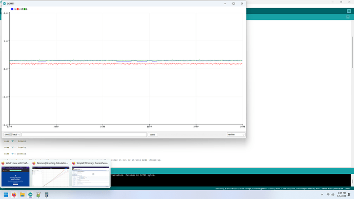
edit: ok so it mostly works, but it seems to give a very similar figure to the one I was using. The red line is the figure derived from the equation in my code above, the blue line is currentsense.getDCCurrent(); It’s not linear and it’s not milliamps, but I will use it anyway as it’s less likely to flake out on me or whatever than my own crackpot code 
I wonder if this approach would work better? I took a few measurments and it seems to be more linear, however it’s still not that good. `
float measure_motor_current(float current_sample){
  static float apparent_current = 0;
  static unsigned long int last_sample_clock = 0 ;
  static float highest_current_lp = 0;// highest current seen in the last period
  unsigned long int period_time = (unsigned long)(_2PI/(motor.target*7)*1000000);//in microseconds
  current_sample = fabs(current_sample);
  if ((micros()-last_sample_clock)>period_time*10){
//    Serial.println((micros()-last_sample_clock));
//    Serial.println(period_time);
        highest_current_lp = apparent_current;
        apparent_current = 0;
  }
  if (current_sample > apparent_current){

    apparent_current = current_sample;
    last_sample_clock = micros();
//    Serial.println(last_sample_clock);
//    Serial.println(micros());
  }
  return highest_current_lp;
}
`
What it does is, hopefully, try to get half of the peak to peak current of the current waveform of a single phase. It has to be called at high frequency to sample the current of a single phase. Obviously it’s less responsive. And the current isn’t actually in milliamps still as the gains of the op amps I would have to adjust for that. Oh well, it’s enough to be getting on with :). As long as I can take measurements during “normal” periods and compare them so I can detect stall. Ideally the actual figure would be in milliamps so I could use the resistance and programmed voltage to detect stall, but doesn’t matter much. I’ll do the stall detection on the pico so it can save a little calibration table, I guess.
Wait no, looks like my approach is giving a similar figure but is just less responsive :
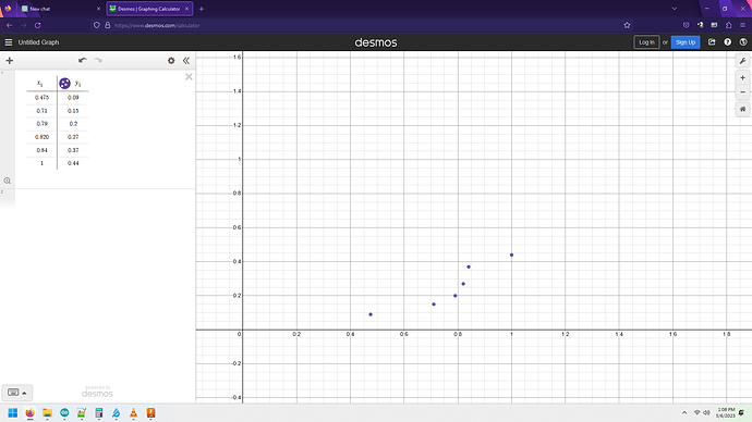
Oh boy, here is a few points of supposed current vs actual measured current (power supply current minus 10 milliamps to account for quiescent current of the board):
Clearly there is a bit of a problem…
Yeah, took some more measurments. The supposed current doesn’t change at all practically in a significant range :
assume 10 mA board quiescent current
0.070  reading, 0.06 to motor 0.34, filtered current-like figure
0.08 0.42
0.11 0.56

0.1 reading 0.09 to motor 0.475 figure
0.13 0.62
0.15 0.67
0.16 reading  0.15 0.71 figure
0.18  0.74
0.21 reading  0.2 0.79 figure
0.22 0.80
0.28 reading  0.27 0.82 figure
0.25  0.8
0.26  0.8
0.29  0.81
0.33 0.82
0.37 reading  0.37 0.84 figure
0.45 readig   0.44  1 figure
You see in the region from 0.21 amps all he way to 0.37 amps the figure hardly changes at all. There is practically no way to extract actual milliamps of DC current from the data, unless what’s happening is that the current is being divided, like a buck converter does. The power supply current may not actually reflect the net current through the motor. I could try multiplying by the internal motor.voltage figure then dividing by power supply, that might give a net current consumption figure…
ok yeah that works pretty well, it’s fairly linear though off by about 15% in some areas with even the best linear formula for correction.


