BTW I have something helpful at least to say about the as5600 white boards. As it turns out the reason for not being able to program them was that the PGO pin was tied to ground with a 1k resistor. I removed R4 and then bingo I have analog out now I am also tryin to play with the internal filter settings of the chip
Something that I don’t understand : when you say “I removed R4 and then bingo I have analog out now”
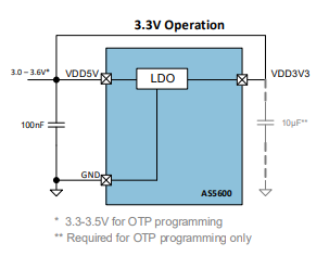
I thought from the datasheet (as not yet tested my board) that in option B mode (with R4 to ground) we should have this behavior : “Analog Output Mode”
By default, the AS5600 output stage is configured as analog
ratiometric output. The Digital to Analog Converter (DAC) has
12-bit resolution. In default mode, the lower reference voltage
for the DAC is GND, while the upper reference voltage is VDD.
So R4 should only prevent to program the chip via I2C ? Am I wrong ?
@Adam_Donovan regarding your noisy motor. Often the motor is only producing 10% of the total noise and what it’s touching is making the 90% of the noise. e.g. the table or chassis it is touching is vibrating. If you hold the motor in your hand is it quieter? If so then mechanical sound damping such as rubber washers may help.
Hey Owen, same noise if I hold it or not:). These are the same motors we always use in the swarm. I will make some new videos to help describe what I am hoping to achieve so stay tuned
@Adam_Donovan, if you are searching for a frequency analyser, go to the play store and load the app “Specroid”. It is really professional, handy and free. Mic and CODEC of most cell phones are pretty high sophisticated.
Probably this brings you an idea what causes the noise. If you have stacked metal sheets in your motor I would look on this usual suspect at first.
I a very interested to find out what is causing the noise too
It would maybe be a good idea to introduce a low pass filter for the position measurement as well as for the velocity.
At the moment it is not included, but this would definitely make sense.
if you would like to try to implement it @Adam_Donovan you could add line:
LowPassFilter LPF_position{0.001}; // time constant 0.001 s
to line 122 of the common/FOCMotor.h and replace line 47 in the file common/FOCMotor.cpp with:
return LPF_position(sensor->getAngle());
Then in your arduino code you can test what is the good value to set to:
Basically the higher tha value the more filtered the angle will be. If you put 0 then there will be no filtering.
So raising this value will start by improving performance and after some value will start degrading it. So there is a sweet spot to hit
I have installed the AS5600 sensor on my motor and tried to run position control code.
My motor is a quite big 14 poles pairs gimbal motor
I power it at 12V
I use an ESP32 (lolin32 lite). This ESP does not have pin 21 exposed. So I have modified wire begin like this
void MagneticSensorI2C::init(){

	//I2C communication begin
	//Wire.begin(I2C_SDA, I2C_SCL);
	Wire.begin(23, 19);
It works and keeps its position quite strongly. I can see the current rising if I try to move the motor. But I do have oscillations.
here is a video showing boot, motion and the oscillations I still have.
I have twiked a little PI parameters more or less efficiently…
I don’t know yet if it is noise on the magnetic sensor position or a bad PID setup ? (or both)
current settings :
 // velocity PI controller parameters
  motor.PID_velocity.P = 0.5;
  motor.PID_velocity.I = 20;
  // maximal voltage to be set to the motor
  motor.voltage_limit = 6;

  // velocity low pass filtering time constant
  // the lower the less filtered
  motor.LPF_velocity.Tf = 0.01;

  // angle P controller
  motor.P_angle.P = 1;
  // maximal velocity of the position control
  motor.velocity_limit = 30;
Is this behavior at the beginning something you expect to have or are these oscillations as well?
This initial movement in steps?
Is the velocity loop more smooth?
You can try removing the interval gain completely PID_velocity.I = 0 and than rising it slowly.
I would certainly suggest you to use the motor commands for this so that you can iterate faster.
You have the library examples with motor commands integrated already.
Huh, it sounds pretty bad then
Honestly, to me it looks like one of the motor phases is unconnected.
I would suggest you to try the velocity and voltage mode first, and make sure that they work well.
You can enable them with motor commands C0 - voltage and C1 velocity mode.
BTW, the velocity was working much better but a kind of wobbling was noticable (not constant speed).
I found the magnet bug with this mode
Thanks for your help
I stumbled upon this message looking for clues as to why my AS5600 on a white board from Ali Express is not giving me any analog or PWM output. If anyone else is struggling with the same issue: It’s because the GPO pin is pulled to ground by R1. Remove it and the analog and PWM outputs should work normally.
Same problem with wrong magnet here with this link. I also had another problem with this board that I want to share. I could not have any stable readings until I fixed the pin DIR to GND, if you leave it floating, you will have a bad time.

")