Hi everyone, i’m starting to set up a stepper motor with you library but i’m stuck at Step 1 (position sensor setup).
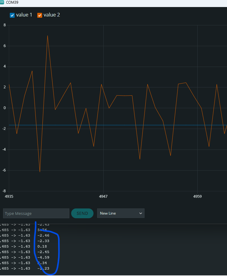
I’m using a magnetic encoder AS5047 connectet over SPI. Using the example provided by the docs page i’m able to check the 6.28 rad if I rotate the shaft by 360° but not able to see the velocity at 0 when the shaft is NOT moving. See the attached picture
The sensor.getVelocity() calls returns a lot of noise.
I checked all the alignment and distance between the magnect vs the sensor and seems ok to me. Distance is 1mm.
Here my code
#include <Arduino.h>
#include <SimpleFOC.h>

MagneticSensorSPI sensor = MagneticSensorSPI(AS5047_SPI, 5);

void setup()
{
  Serial.begin(115200);

  sensor.init();

  Serial.println("Sensor ready");
  _delay(1000);

}

void loop()
{
  sensor.update();
  // display the angle and the angular velocity to the terminal
  Serial.print(sensor.getAngle());      // angle is correct
  Serial.print("\t");
  Serial.println(sensor.getVelocity()); // the velocity never go to 0 when the encoder is stopped but continue to

}
Do you not see any velocity movement at all or is it just very noisy when you do not move the shaft?
What microcontroller are you using?
If you are using a esp32 or a stm32 boards, they might have a very fast loop times and the velocity might be noisy.
There are two ways to get a better velocity reading:
You could potentially add a small delay in the loop function to get more time between the sensor.update(). This will give a bit more time for the shaft angle to change and produce a better velocity estimate. BEWARE: Do not use delay functions once you run the complete stack with the driver and the motor, it can have a significant negative effect on the precision and performance in general.
Another way (preferred) of achieving similar behaviour is to set the sensor.min_elapsed_time variable to a higher value (by default it’s 100us - 0.0001, you can try setting 1-5ms). See a bit more info in the docs
This variable basically sets the minimum time difference between the velocity calculations. If the sensor.update() (velocity is calculated inside this function) is called more often than this time, the velocity will not be calculated at each call.
Motor: Nema 17 (dont know the specifications, grabbed from an old 3d printer)
Driver: Custom board based on dual chip DRV8870 (One per phase)
I tried your suggestion by using the instruction sensor.min_elapsed_time = 0.1.
You suggest to use a value around 0.001-0.005 but with this range I still observe noise from the sensor. Do you see some downside using a value of 0.1?
That would imply only 10 updates per second - far too few… the timers are a bit inaccurate, but not that inaccurate. You want the sensor to update with more than 1kHz, I think.
If you want to smooth out the result you can use the low pass filter class.
But I think your results are quite noisy. Is the magnet maybe too far from the sensor, or the motor magnets too close?
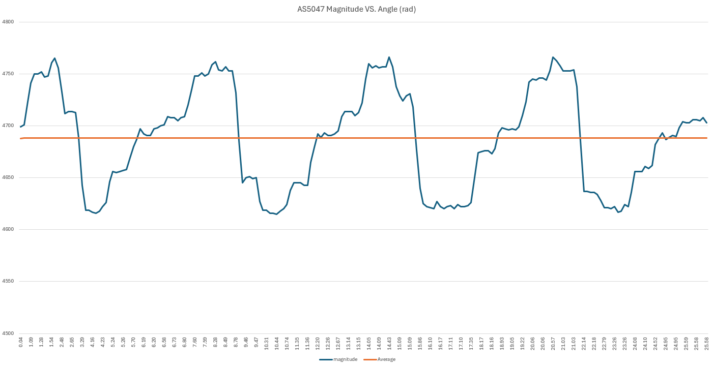
What value do you get from the magnitude register? (You can use the dedicated AS5047P driver from our drivers library to read the other sensor registers)
Yes, I think 4700 is good, that’s around the value I get on other setups that have worked…
It’s hard to say what the problem is. Velocity noise is normal for the reasons Antun mentioned. Maybe your setup has very good bearings and low rotor inertia/load so it “jitters” more when idle.
You could try fine-tuning PID and LPF to see if you can reduce it with tuning, but if the motor is unloaded, often adding some load/dampening will help a lot against the 0 velocity jitter.
And when the motor is actually being driven and moving, then the velocity error is usually lower, so another trick can be (if the application allows it) to just disable the driver when you want to idle at 0 velocity, and only enable it when you want to move.
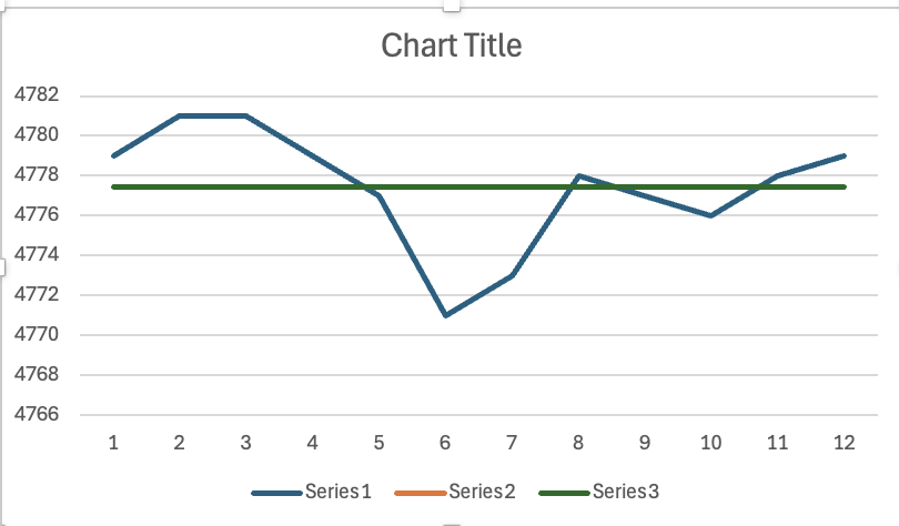
I find sometimes that plotting the values against their mean gives some clues. eg I plotted just the few values you posted above, and it looks vaguely sinusoidal. Try it with a larger set and see if something jumps out.
@runger Please consider that the motor is not actually connected to the voltage. I’m actually testing just the sensor so i don’t think is related to any PID settings or inertia. Correct me if I misunderstood.
@motormaker Thanks! I will try again after work and I will post the plot of the values
@motormaker I tried plotting some full revolutions magnitude readings and… you are right. The readings show up a sinuisoidal output coming from the sensor. Maybe the magnet is aligned but a little tilted.
The reason I had asked to see if sinusoidal/periodic is because now we can see that the “wavelength” of the oscillation is quite consistent, whatever the cause.
By finding the typical time difference from beginning to end of each wave (or the number of loop iterations of your main loop), this essentially gives you precisely how many cycles to average the signal over, because that will result in what is now visible as the mean. If many such intervals fit inside 1ms, then it may be sufficient.
Since you don’t have a very high rpm requirement, this may be easier than replacing your sensor setup.
TBH no. If that were the case you’d expect the magnitude to vary also when the motor isn’t moving. That it varies as the magnet turns, it’s expected, although your variation seems a lot.
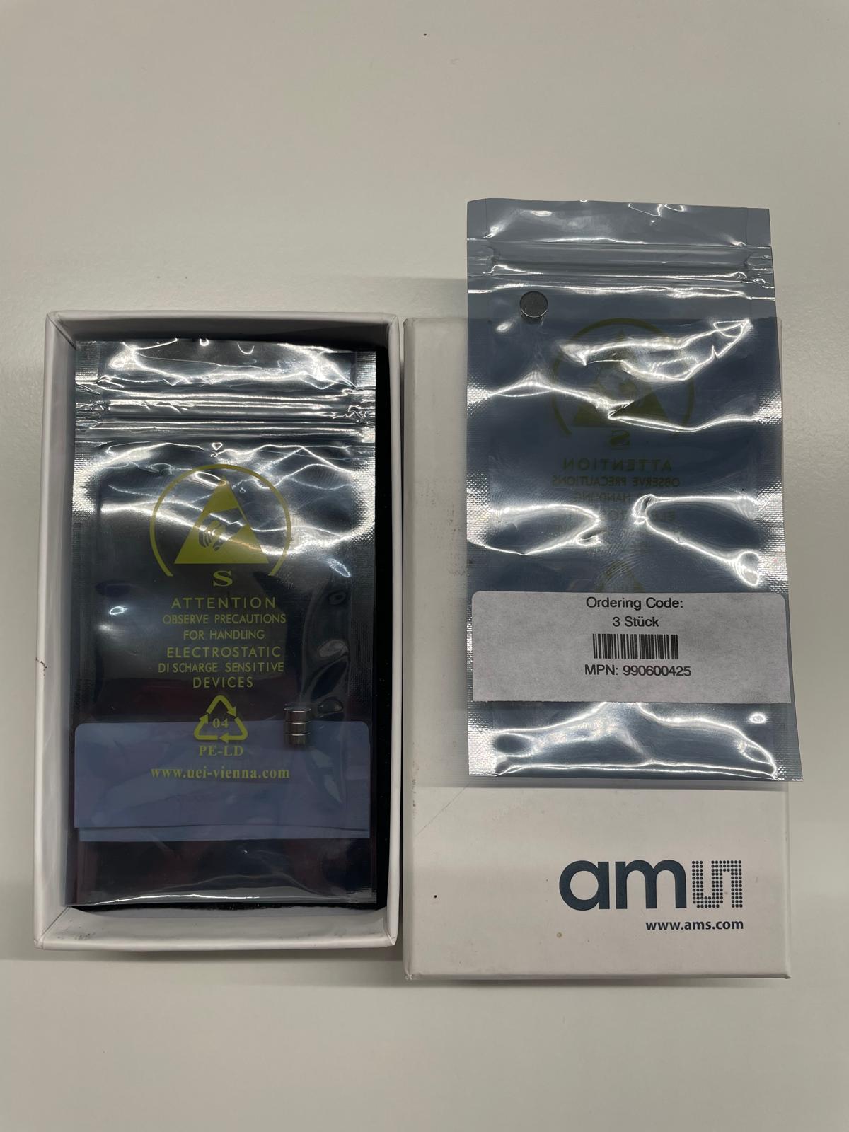
Are you sure it’s a good magnet? Is it from a reliable source? Can you test with another one, or check it with a magnet viewer?
It’s a “genuine” magnet from AMS company (AS5000-MD6H-3 Diametric Magnet, D6x2).
Anyway I tried differents magnets (AS5000-MD6H-3) but everyone show the same results.
Only by using the ABI interface of the AS5047 I was able to get velocity = 0 without noise, but of course ABI interface only has 2000 CPR, so maybe thats why I dont see any noise.
Next week I will try other sensor/encoder and I will post the results.