Angle mode operation gets worse after several rotations

Hi everyone, recently found SimpleFOC while researching PID motor control libraries for a project.

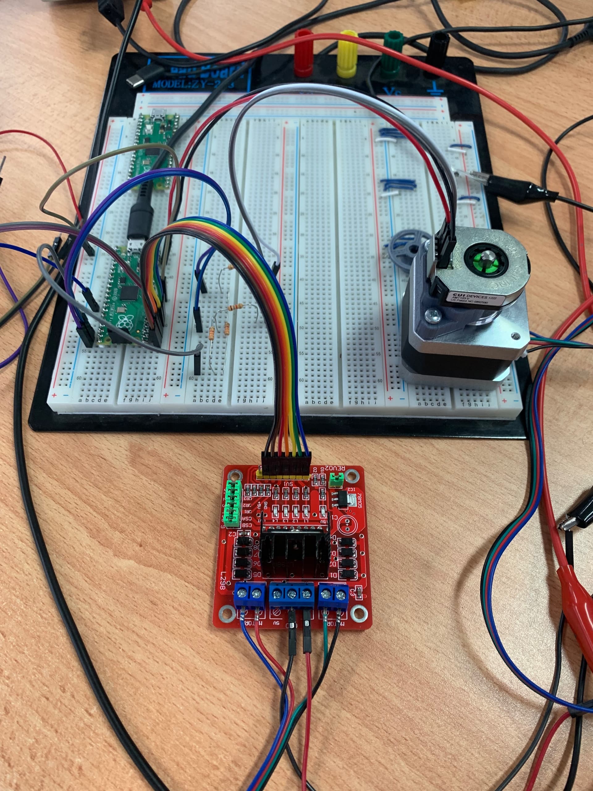
I have a setup consisting of a Pi Pico, a L298N driver board, a NEMA17 stepper, and an AMT103 encoder. I’ve managed to get everything configured and running, and I’ve also set up live control with SimpleFOCStudio.

The problem is when I run the motor in angle (closed-loop) mode. I set my increments to 6.28 rads in SimpleFOCStudio and I have been testing single and double rotations. If I keep incrementing in the same direction, the motor’s response is snappy and smooth for the first three or so rotations, but after that each successive rotation gets a little slower, a little noisier, and draws more current. This can get so bad after about ten rotations in one direction that the motor is basically at a standstill and drawing 1-2A from my 12V Power Supply.

BUT if I switch directions, it very quickly becomes snappy and smooth again, with power consumption as it should be. However if I continue in this direction the motor starts struggling after a few rotations again.

This has me baffled. I first thought that maybe the encoder is misconfigured and just slightly off, but I have manually confirmed that the encoder is accurate (I tested this by doing exactly 10, 20, 30 rotations by hand and double checking the reported angle). It’s almost as if there’s some kind of rotational slack present somewhere that isn’t being accounted for?

I’m aware of the limitations of the L298N due to its slow switching characteristics, but I have been running these tests at slow speeds and within those first few rotations in either direction the performance is great. The only other thing possibly harming me is I’m not using the index channel on my encoder but if my reported angles are accurate I don’t see why that should be a problem.

I’m at a loss what to do now. Any insight as to what’s happening would be greatly appreciated.

Below is my code and a picture of my setup. (Pi Pico running Arduino Framework through PlatformIO)

#include <Arduino.h>
#include <SimpleFOC.h>


// Stepper motor & driver instance
StepperMotor motor = StepperMotor(50, 1.5); // Pole pairs, Phase resistance
StepperDriver4PWM driver = StepperDriver4PWM(p20, p19, p18, p17, p21, p16); // A+, A-, B+, B-, enA, enB

// Encoder instance & callbacks
Encoder encoder = Encoder(p14, p15, 2048); // A, B, Set PPR (see DIP switches inside encoder)
void doA(){encoder.handleA();}
void doB(){encoder.handleB();}

// instantiate the commander
Commander command = Commander(Serial);
void doMotor(char* cmd) {command.motor(&motor, cmd); }

void setup() {

  // encoder config
  encoder.init();
  encoder.enableInterrupts(doA, doB);
  // link the motor to the encoder
  motor.linkSensor(&encoder);

  // driver config
  driver.pwm_frequency = 32000;
  // power supply voltage [V]
  driver.voltage_power_supply = 12;
  driver.init();
  // link the motor and the driver
  motor.linkDriver(&driver);

  // limiting motor current (provided resistance)
  motor.current_limit = 1.7;   // [Amps]
  motor.voltage_sensor_align = 5; // aligning voltage
  motor.foc_modulation = FOCModulationType::SpaceVectorPWM; // choose FOC modulation (optional)
  motor.LPF_velocity.Tf = 0.01; // velocity low pass filtering time constant
  motor.velocity_limit = 50;

  // controller configuration based on the control type 
  motor.PID_velocity.P = 0.2;
  motor.PID_velocity.I = 20;
  motor.PID_velocity.D = 0;
 
  // open loop control config
  motor.controller = MotionControlType::angle;

  // init motor hardware
  motor.init();
  motor.initFOC();

  // add target command T
  command.add('M', doMotor, "Full Motor Config");

  Serial.begin(115200);
  Serial.println("Motor ready!");
  _delay(1000);
}

void loop() {
  
  motor.loopFOC(); // FOC algorithm
  motor.move(); // Motor control loop
  command.run(); // User communication

}

Interesting, farther than I got for sure. It sounds like a problem with the code base. If you connect things and follow the instructions and it doesn’t work, there is a problem with the underlying systems. I didn’t even know it worked with the pico. Perhaps you can write a tutorial when you are done.

I think the pico is an important part of the future and we should embrace it, even the silicon design is supposedly open source (although I haven’t seen the source).

can you swap in an arduino and see if it works?

Hey @thewrongbutton,

This is an interesting problem. In my opinion it is the misalignment due to the sensor drift.
The issue is that the stepper motors are very sensitive to the misalignment and as they have 50 full electrical rotations per one mechanical shaft rotation or in other words each 7.2 degrees one full electrical revolution. The BLDC motors usually have 7-10 pole pairs (electrical revolutions per mechanical revolution) so if there is a slight misalignment happening between the sensor and the motor it is less visible.

So in your case I think that the Pico is probably missing some encoder impulses which makes it increasingly impair the alignment with the motor’s shaft angle over time. This is consistent with your findings as it’s effect would bee seen much more in one direction than in the other.

I would suggest you to use the index pin if you can because it will help correct this error.
However, I am pretty sure that you can make it work without it also.
There are couple things you can try

  • make sure that the encoder is properly fixed and that there is no slack
  • try changing the encoder’s pulse count ( amt103 ) allows you to do this with 4 switches inside the metal enclosure- I think by default you have 2048 pulses, try with lower values to see if the behavior is less pronounced

You can also verify that this behavior is due to the alignment issues by running the motor in the velocity mode and setting a lower velocity value and letting the motor spin. If it stops at some point this means the alignment has been lost. You can then try to move (if it has some sack) a bit your encoder by hand in one and the other direction and you motor should move a bit. You will be reducing the alignment error by moving the sensor a bit. :smiley:

@Anthony_Douglas For this project I simply used PlatformIO.
Started a new Pico project with the Arduino framework, then added the simplefoc library through PlatformIO’s library browser. Then I mostly copy-pasted example code from the docs with a couple of Pico-specific changes like pin names and it was working rather quickly.
It’s so similar to using an Arduino board that I don’t really think a tutorial would be necessary, although to be fair I haven’t used the Arduino IDE for a while, I’ve been using PlatformIO exclusively for over a year for all my mcu code and like it a lot more.

@Antun_Skuric I think you’re definitely onto something with the Pico potentially missing pulses. I originally started with the Encoder at full resolution (4096 ppr) but quickly changed to half that at 2048 which I’ve been running ever since. (I also lowered the PWM frequency to 5kHz after researching the L298 on this forum)

The biggest change that improved performance was actually running the Pico standalone rather than having it connected to SimpleFOCStudio. I suspect one of two possibilities:

  1. The Pico’s use of serial communication was causing timing problems with the encoder channel interrupts. (So potentially a Pico-specific library quirk / hardware limitation)
  2. My laptop did not like the serial connection (other peripherals would sometimes connect and disconnect randomly while my board was connected through SimpleFOCStudio) and was potentially causing hangs which messed with the Pico’s interrupt routines (I have not researched the RP2040’s interrupt priority hierarchy)

Or perhaps it’s a combination of both.

I have since changed to standalone operation, with a potentiometer controlling the motor position and things are working much better to the point where I can actually start doing some PID tuning. (Unfortunately this means recompiling and reuploading for every PID tweak) I will definitely be changing a few things though:

  • Hooking up the Index channel on the encoder
  • Halving the resolution of the encoder again to 1024
  • Verifying the alignment of the encoder after a large amount of rotations
  • Probing the Encoder channels to check the integrity of the signal pulses (I have to run them through a voltage divider because the Pico’s IO pins are not 5V tolerant)

… And just as I wrote that last sentence I realised that the logic side of the L298 board is 5V and my Pico PWM outputs are 3.3V :neutral_face:… So I’m potentially making the L298’s switching times even slower than normal…

Anyways thank you for the insight and I’ll report back after implementing these changes.