Hello everyone,
My objective is to build the world’s most springy, smooth, and compact gimbal BLDC motor (direct-drive)–driven robot arm using SimpleFOC, and this post marks my starting point. I have chosen the T-Motor GB series motors for this project.
I would like to share my current results and gather any meaningful advice you are willing to offer on how I can improve my SimpleFOC implementation for gimbal BLDC motors, specifically for position and velocity control.
I am also interested in learning about any proven, reliable BLDC drivers (up to 24 V and with built-in current sensing) that you use frequently and would recommend. My design philosophy would be to use a MCU and a driver along with all the bits on each motor hooked to a central MCU via SPI/UART to interface with my ROS2 PC with a USB A cable.
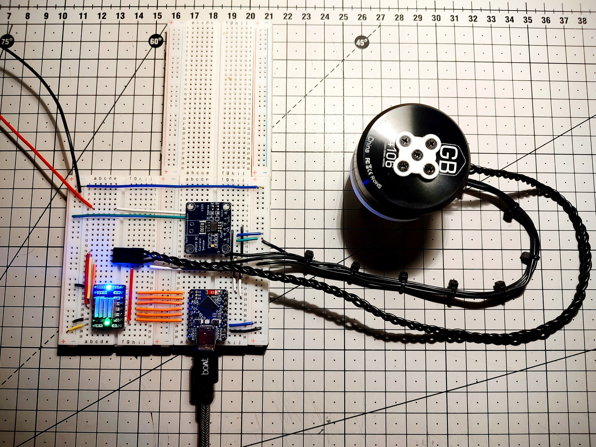
At the moment, I am working with the following hardware:
-
T-Motor GB4106
-
TMC6300 (three-phase driver)
-
Osram AS5600 (encoder)
-
ESP32-S3 Zero (a.k.a. the mini version)
-
INA219 (current sensor)
I havent decided on what electronics I would go with, again I will start with the best Motor driver and discover the other stuff on the way.
At the moment here are my results.
Here is the code (Below) I have developed based on the tutorials. It is functional and has been thoroughly tested. Below, you will also find several PID charts that I generated using a Python script. The methodology was to move the motor from Position A to Position B, capture the encoder data, and plot it on a graph. This allowed me to tune the PID parameters to achieve the smoothest possible motion.
I would appreciate any feedback on the PID graphs as well, particularly suggestions on how they could be further improved.
The command parameters used are:
- Target angle
- Velocity P
- Velocity I
- Velocity D
- Velocity LPF
- Angle P
- Voltage limit
#include <SimpleFOC.h>
#include <Wire.h>

// ---------------- Pins ----------------
const int phU_h = 11;
const int phU_l = 12;
const int phV_h = 9;
const int phV_l = 10;
const int phW_h = 7;
const int phW_l = 8;

// ---------------- Motor ----------------
// 12N14P motor → 7 pole pairs
BLDCMotor motor = BLDCMotor(7);

// ---------------- Driver ----------------
// TMC6300 → 6PWM
BLDCDriver6PWM driver = BLDCDriver6PWM(
  phU_h, phU_l,
  phV_h, phV_l,
  phW_h, phW_l
);

// ---------------- Sensor ----------------
// AS5600 via I2C
MagneticSensorI2C sensor = MagneticSensorI2C(AS5600_I2C);

// ---------------- Commander ----------------
Commander command = Commander(Serial);

// -------- Commander callbacks --------

// Angle target (radians)
void doAngle(char* cmd) {
  command.scalar(&motor.target, cmd);
}

// Velocity PID tuning (still used internally!)
void doVP(char* cmd) { command.scalar(&motor.PID_velocity.P, cmd); }
void doVI(char* cmd) { command.scalar(&motor.PID_velocity.I, cmd); }
void doVD(char* cmd) { command.scalar(&motor.PID_velocity.D, cmd); }
void doVLPF(char* cmd) { command.scalar(&motor.LPF_velocity.Tf, cmd); }

// Angle PID tuning
void doAP(char* cmd) {
  command.scalar(&motor.P_angle.P, cmd);
}

// Voltage limit
void doVlim(char* cmd) {
  command.scalar(&motor.voltage_limit, cmd);
}

void setup() {
  Serial.begin(115200);
  delay(1000);

  // ---------------- I2C ----------------
  Wire.begin(6, 5); // SDA, SCL

  // ---------------- Sensor ----------------
  sensor.init();
  motor.linkSensor(&sensor);

  // ---------------- Driver ----------------
  driver.voltage_power_supply = 10.4;
  driver.init();
  motor.linkDriver(&driver);

  // ---------------- Control mode ----------------
  motor.controller = MotionControlType::angle;

  // ---------------- Angle PID ----------------
  motor.P_angle.P = 25.0;   // start here (typical range 5–20)

  // ---------------- Velocity PID (inner loop) ----------------
  motor.PID_velocity.P = 0.5;
  motor.PID_velocity.I = 0.1;
  motor.PID_velocity.D = 0.001;

  motor.LPF_velocity.Tf = 0.02;
  motor.PID_velocity.output_ramp = 300;

  // ---------------- Limits ----------------
  motor.voltage_limit  = 10.4;   // VERY important in angle mode
  //motor.velocity_limit = 20.0;  // limits snap speed

  // ---------------- Monitoring ----------------
  motor.useMonitoring(Serial);

  // ---------------- Init ----------------
  motor.init();
  motor.initFOC();

  // ---------------- Commander ----------------
  command.add('A', doAngle, "Target angle [rad]");
  command.add('P', doVP,    "Velocity P");
  command.add('I', doVI,    "Velocity I");
  command.add('D', doVD,    "Velocity D");
  command.add('L', doVLPF,  "Velocity LPF");
  command.add('Q', doAP,    "Angle P");
  command.add('V', doVlim,  "Voltage limit");

  Serial.println("=================================");
  Serial.println("Closed-loop ANGLE FOC READY");
  Serial.println("Commands:");
  Serial.println("  A <rad>  - target angle");
  Serial.println("  Q <val>  - angle P");
  Serial.println("  P/I/D/L  - velocity PID");
  Serial.println("  V <volt> - voltage limit");
  Serial.println("=================================");

  delay(1000);
}

void loop() {
  // -------- FOC loop --------
  motor.loopFOC();

  // -------- Angle control --------
  motor.move();

  // Print velocity (optional, for debugging)
  Serial.println(sensor.getAngle(), 6);

  // -------- Commander --------
  command.run();
}
PID Graphs results: This was captured Raw encoder values converted to radians vs time stamps. Here’s a video to demostrate the “Return to Position“.
Link to the Graphs - Google Drive
Heres the initial setup.
Have a nice day,
~Roland