
good night does anyone know how to set up an acs712-30A as current sensor? another question, is necessary to remove the diode diode from the circuit? I am using the PB0 and PB1 ports for THE CURRENT SENSORS ANY PROBLEM IN THIS ?
Good morning @marcusbeche !
Where is this schematic from? Is it your design? Do you know what type of diode this is?
I don’t quite understand the idea of the diode, I must admit. From my point of view this will cause C13 to charge, but not discharge (except via the current sense pin)? Is this circuit known to work?
PB0 and PB1 of which MCU type?
Good morning @runger
diodes are 1n4148 and the CPU is ST32F103C8. You’re right. should have a discharge resistor I forgot to put it. I think I should remove the diode. What do you think of that? thanks for the remark.
That diode there is wrong. Also having a resistor, depending on size and where you put it, will turn the circuit to an RC filter at best and useless at worst.
Remove the diode, and leave the 100nF there as a decoupling capacitor and place it as close next to the analog pin of the MCU as possible. Also, depending on your motor speed, 100nF may be too large at high speeds, and worsen your timing, may want to go for 10nF — I see you already put a 1nF filter directly into the sensor anyways.
Third, I see you feed 5V and pull 3.3V, you must ensure the voltage divider is using 0.1% or 0.05% high precision, extra low temperature distortion resistors, which are quite expensive, and also you need a reference divider circuit with the exact same resistors, depending on your MCU for analog reference signal. Also, using a voltage divider, the decoupling capacitor, in combination with the resistors from the divider, depending on the length of the trace and its inductance, will still act as an RLC filter anyway, so be prepared for some signal delay. That’s not a bad thing, you will get a smoother signal, just be prepared about what to expect from this.
Not sure what you mean by this.
Cheers,
Valentine
Thanks SO MUCH for your help, @Valentine. great observations. I will implement. Thank you very much
Hey @Valentine , do you have experience with using the ACS712 while powering it with 3V3?
I want to use this sensor with Nucleo32G431KB.
Do i have to power the current sensors with 5V and use the voltage divider network, or would the 3V3 approach be also ok?
I tested the ACS712 with 3V3 (from the internal Nucleo LDO), and the sensors give a good reading (±10mA from target), although the sensitivity went from 100mV per Amp, to 60mV per Amp. I can test only on DC current, so i dont know what will be the impact on faster readings, while measuring current on motor phases.
What power structure for sensors and Nucleo to use, to ensure good voltage reference on sensors and AVDD pin?
I wanted to power the 3 ACS712 sensors and Nucleo with the same 3V3 LDO.
Additionally i have 3 Hall Sensors that are powered with 5V LDO, and additional 3V3 LDO for pull-up resistors. The LDO’s for Hall Sensors only power the Hall Sensors, in order to provide a switching digital signal with its own power supply, separated from the analog devices.
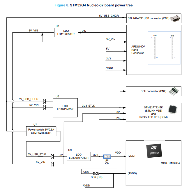
I was analyzing this power tree but im not sure about a good power structure.
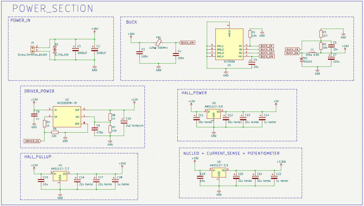
The power structure in my project looks like that:
So far i am not using the AVDD pin, only providing power to the Nucleo through the 3V3 pin.
I’m not sure if that’s correct, becouse on the STM32G4 power tree schematics, it looks like 3V3 is supplied to the AVDD and VDD by the internal LDO, only if using 5V or VIN pins to supply the Nucleo.
I will be grateful for any help.
I’m surprised!
The sensor’s datasheet gives the minimum supply voltage as 4.5V. For it to work at 3.3V is surprising.
On the one hand, you might say if it works, it works, but personally I would not be comfortable with this. Underpowering your chips is also a good way to get weird and hard to debug errors. I’d be concerned about the reliability.
Why not use the voltage divider or an op-amp to take the ACS712’s output down to 3.3V instead?
Regarding the power tree:
It looks ok to me in principle, looks like you took a lot of care to keep everything separate.
May I ask why you’re using the tantalum capacitors with 22uF on the 3.3V and 5V power rails? The datasheet does mention using them, but won’t this make the project quite expensive? And it’s quite a lot of capacitance.
It should be easy to find some LDOs which are stable with just a normal ceramic capacitor? 22uF ceramics are available in sizes down to 0603 for 16V…
But going from 15V to 3.3V and 5V is wasting a lot of power?
Personally, I’d perhaps make it one step simpler by using a 12V buck, for the driver, and a 5V buck for the halls, and then 3.3V LDOs from the 5V rail. This will be more efficient, I think. The hall pull-up power and MCU could be the same LDO for me, but I’d consider putting the analog part on its own LDO with some extra filtering.
I guess the ACS712 is a pain in that regard because you’d have to power it from the noisier 5V buck, but want the signal to go to the AVDD domain. It would really be nicer to find a 3.3V current sensor…
Thanks for the answer @runger you are right about the ACS712, but i very like the fact that it provides isolation in a simple to use package. I would want to find something similar but 3V3 powered.
EDIT : found the ACS725 basically ACS712 on 3V3, didnt know it exists but mouser proved me wrong.
I mainly wanted to simplyfy the project as much as possible, even if that would mean higher cost.
That would be my first esc-pcb, so i try to play it safe and might commit an overkill in some aspects.
The 15V to 5 or 3V3 reduction is not ideal i agree, i have to do something about it. I am just worried about the switching noise from the buck, and also reflections on hall sensor wires (around 0.5m long) causing TVS. So i separeted the power sources and made all components have an LDO in series after the buck. Also i wanted to be able to toggle the drivers on/off with their own LDO.
If i would use a buck to power the drivers and hall sensors, wouldn’t that make these components more susceptible to interference from the switching and fields around?
Can the hall sensor switching + wires, incluence the power integrity for the Nucleo to cause problems, if Nucleo and hall pull-ups are on the same LDO? The termination and filtering might not be on point at first.
Fair enough!
I think you are probably right. Certainly another LDO in-between would provide another level of regulation, and there are some pretty good LDOs if you want to get fancy.
I will say that your power tree is more complicated and careful than any of the drivers that has been shown in our forums so far. So maybe it is a little bit overkill?
But it certainly makes sense to be concerned about the analog and sensor signals. Many people have problems with unclean signals.
You could look at some of the driver boards from ST-Micro or Texas Instruments. Many of them have schematics, or you can find the schematics online. A board like the B-G431-ESC1 is even using the same MCU family as you… perhaps you will find some more guidance there?