My motor controller board is going to be in a electrical cabinet of some sort. So i would have to bridge a distance of about 5-10m to the actual encoder.
My goal would be to use a absolute encoder from the ams AS series (5147 or similar).
The only solution i could come up with is to put a separate MCU on the encoder board at the motor and convert the SPI from the encoder to UART and then via rs435 to the motor driver board And on the driver board back to UART.
This would be a little complex setup so I’m asking if anyone has a better idea to solve this.
As always, thanks for the help.
Use canbus with a shielded twisted pair. It’s terrible as hardware, you need to design your own hardware pcb and custom code development but that’s what canbus was originally developed for. The maximum bus length with a bit rate of 10 kbit/s is 1 km, and the shortest with 1 Mbit/s is 40 meters. The alternative is to spend some money and buy a canbus module such as this:
I have not personally used it, so no idea how it works.
This is my module I created some time ago, uses SPI to communicate with the MCU, and you are insulated from all the nastiness of the can implementation.
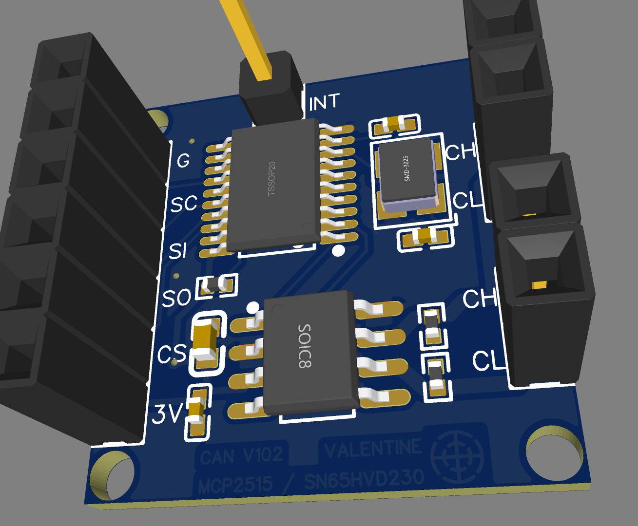
This is the SPI CanBus library
One of the resistors (the lower one on the canbus side) is supposed to be left out to create a solder pad for shunting to enable the 120ohm termination resistor in case the particular node is considered a terminating line node. I can send you the gerbers and bom and pnp if you decide to go that way.
So if i get this right, i go from encoder SPI to some MCU then to UART to the can ic over a cable to the can ic on the motor controller back to UART into the main mcu.
You have two choices:
-
Off the shelf Seed board module: SPI encoder -> your code to translate angle/velocity to TX/RX CAN frame -> Seed module 1 -> Twisted pair cable -> Seed module 2 -> your code to translate TX/RX CAN frame back to angle/velocity signal
-
My SPI board: SPI encoder -> your code to translate angle/velocity to SPI CAN frame -> SPI/CAN board 1 -> Twisted pair cable -> SPI/CAN board 2 -> your code to translate SPI CAN frame back to angle/velocity signal
The difference is that in case #1 you use TX/RX which is built into the core code of pretty much any MCU and the case#2 you need to use the thirs party SPI/CAN library.
Also you need an MCU with two SPI busses. I am using STM32 which has two busses, no problem, I dedicate one bus for the sensor and another for the SPI/CAN. The difference is that TX/RX is very slow, at most you can get to 115200 baud without any monkey business, however, SPI is up to 10MHz fo you will first saturate the CAN before you saturate the SPI bus, which is good. Generally the CANBUS could be utilized up to 30% signal saturation before you start getting error frames in the base case and up to 80% in modern implementations. That’s why it is generally preferable to leave the low lever handling to a middle man rather than solving this with a bare MCU and transceiver. If you notice, the Seed module has an atmel chip with code inside already handling all that nasty business and you are guaranteed clean frames. Same with the SPI MCP2515T-I/ST module. Actually the Seed goes a step further, I guess, because they already use MCP2515T-I/ST which is piped via SPI to the atmel chip and then you connect to the atmel via tx/rx. That Seed solution however may be too slow for your case since you control a motor, and I have no idea of the latency either, must be unusable for fast angular sensor. Currently I am working on a solution where I handle CAN directly via a transceiver and this is a real pain in the back because I need fast speed and no latency. However I think the MCP2515T-I/ST would be good enough. Watch out for the latency however.
Edit: You could also try Option 3, MCU directly to transceiver if it has built-in CANBUS but that’s like bringing a knife to a gun fight. I made it work on stm32f103 and my butt is still hurting.
so like this:
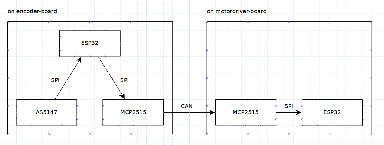
esp32 has 2 usable spi ports, it also has CAN but it seams quite complicated to me.
There are also librarys to use the esp32 internal can so i just need a tranceiver
That seems about right. I have absolutely no experience with Espressif’s ESP32, however there is another thread on this board, you may find some useful info:
https://community.simplefoc.com/t/can-bus-interface-simplefoc-standard-identifiers/577
I believe they managed to connect a transceiver directly to the MCU and run data frames.
You need to be careful however because the angle sensor latency at high RMP will create issues if you plan to use it for FOC. I am not sure exactly how you plan to use the signal, I am assuming you only need to monitor the motor and not using the second remote board for FOC control and use the first board just for the sensor. Because you say motor driver board for the remote board, and that would also mean your phase power cables will be long, and that creates its own problems in addition to angle signal latency.
Running BLDC signals over 10 meters is a big no no to me. how big is your motor?
rule of robotics, power and low level signal as close to the drive as you can get it.
I don’t think this is even conceivable to run the angle sensor for real-time FOC over 10 meters if this is indeed the case.
@Adam_Donovan Maybe 10m is a bit exaggerated( i think 3m is more realistic), but I’m kind of trying to make a motor driver that does it all. From hoverboard motors to asynchronous motors (so it’s just a vfd) 24V DC to 230v AC input at max of about 20A.
I basically want to replicate something like this more or less: https://a.aliexpress.com/_vWGHzu
This thing has 3m cable so that should be fine.
still how big is the motor…much better todo all foc and drv as close as possible
@Adam_Donovan Like physical dimensions or electrical?
I bet $100 this has a control board inside that motor and the outside box is just controlling the RPM and whatnot.
The Siemens servo drives we use at work have a cable length of at least 10m but I ain’t Siemens engineering so I’m satisfied with less🤣
If you open the servo you will find the control board inside. The 10m cable is for high level control. The low level is done inside the motor housing. That big control box is for controlling multiple servos simultaneously for whatever manufacturing process you got. I am talking about the siemens ones. The one from aliexpress I am only willing to bet, and I may lose.
Edit: Some siemens drives eare running RS-422 for the sensors, but that’s an industrial level protocol and you need very expensive hardware design to do that.
Here is a yaskawa servo driver and motor teardown, the power electronics are in the external motor driver and the motor is just a bldc motor with a encoder/resolver
still if its a big motor the weight of the controller is minimal so closer as to avoid noise and also has the benefit of less wires to your motor
Better even mount the angular sensor directly on the control PCB.
Here is something I found but have no idea how to interface the sensor to it
I think I found the part that is going to make this incredible easy https://www.mouser.de/datasheet/2/609/LTC6820-1601976.pdf
Just have to find it in stock 

